


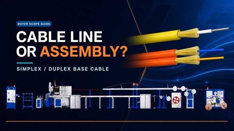
A fiber optic cable factory owner, production manager or technical buyer planning conventional patch cords must define two connected scopes. One scope makes the simplex or duplex base cable; the other cuts that cable and turns each end into an inspected, optically tested connector assembly.
A complete fiber optic patch-cord factory is not one extrusion line. It is either a qualified purchased-cable supply plus a complete connector-assembly workcell, or an integrated route that adds tight-buffer and outer-jacket production before the same back-end workcell.

구매자 범위도: 케이블 생산 라인은 심플렉스 또는 듀플렉스 베이스 케이블을 제조하며, 별도의 커넥터 조립 작업셀에서 해당 케이블을 완제품 LC 또는 SC 패치 코드로 가공한다.
This guide maps the complete manufacturing boundary for conventional LC and SC patch cords. FC and ST may be added as project-specific fixture variants, but they are not the main production scope in this article. MPO and MTP multi-fiber assemblies are excluded because their cable construction, ferrule preparation, polishing, geometry control, polarity and multi-channel testing require a separate project scope.
완전한 패치 코드 공장에는 무엇이 포함되어 있습니까?
A complete patch-cord route must end with a saleable, traceable connectorized product—not merely a reel of cable or a visually polished connector. The proposal needs an owner and acceptance record for every stage from incoming fiber or cable through final optical test and packing.
| Manufacturing boundary | 입력 | 주 출력 | 출하 전 증거 |
|---|---|---|---|
| 베이스 케이블을 자체 제조할 경우의 타이트 버퍼 생산 | 승인된 광섬유 및 버퍼 컴파운드 | 자격을 갖춘 타이트 버퍼 피복 광섬유 | 재질 식별, 치수, 표면 상태 및 합의된 광학 검사 |
| 기본 케이블을 자체 제작할 경우 아라미드 및 외부 재킷 생산 | 승인된 타이트 버퍼 피복 광섬유, 아라미드 및 재킷 혼합물 | 릴에 감긴 심플렉스 또는 듀플렉스 케이블 | 케이블 드로잉, 치수, 릴 식별, 외관 및 합의된 광학 검사 |
| Cable preparation | 방출된 릴 또는 구매한 적격 케이블 | 절단 및 준비된 케이블 단자 | 길이, 방향, 스트립 치수 및 트래블러 식별 정보 |
| Connector assembly | 준비된 케이블, 커넥터 부품 및 승인된 소모품 | 조립 및 경화된 커넥터 단부 | 부품 로트, 공정 설정 및 배치 또는 작업자 기록 |
| 연마 및 단면 검사 | 안정화된 커넥터 어셈블리 | 페룰 단면 청소 | 승인된 연마 공정 및 저장되거나 추적 가능한 검사 결과 |
| 광학 테스트 및 마감 처리 | 완성된 패치 코드 | 출고 가능한 제품 | 시험 설정, 파장, 결과, 식별, 라벨 및 포장 기록 |
그만큼 HONGKAI patch-cord cable production line supports the base-cable side for applicable constructions. The confirmed project route then adds partner-integrated back-end stations, together with connector-specific fixtures, hand tools and consumables. HONGKAI’s published 제조 및 전문가 통합 모델 explains this source boundary; the final commercial proposal must still distinguish HONGKAI-manufactured equipment, partner-integrated equipment and buyer-supplied items.
Common mistakes: A quotation calls the cable line a complete patch-cord factory but omits connectorization and optical testing. Another quotation lists a polishing machine but omits its connector fixtures, films, inspection adapter, reference cords or process responsibility.
어느 HONGKAI 라인이 기본 케이블을 만드는가?
For the reviewed simplex or duplex construction, the HONGKAI route uses the HK-30 to produce tight-buffered fiber and the HK-50 to apply aramid reinforcement and the outer jacket. If the factory purchases qualified tight-buffered fiber, the cable-making scope can start with the HK-50.
HK-30 타이트 버퍼 스테이지
The reviewed HK-30 configuration receives optical fiber and applies the specified tight-buffer layer. Its functional modules include controlled payoff, preheating, material drying and feeding, extrusion, warm and cold cooling, online diameter measurement, capstan control and take-up. These functions define the production stage; the customer’s approved construction must define the actual polymer, color, dimensions, reel format and acceptance limits.
Verified HONGKAI HK-30 3D reference showing the complete tight-buffer production line. Final tooling, material and operating values remain project-specific.
HK-50 aramid-and-jacket stage
The reviewed HK-50 configuration receives the approved tight-buffered input, pays off the aramid reinforcement and extrudes the outer jacket. Its functional modules include input payoff, adjustable aramid payoff, positioning, material preparation, extrusion, cooling, online diameter measurement, capstan, accumulation and take-up.

Verified HONGKAI HK-50 3D reference showing the complete line used for an applicable aramid-reinforced simplex or duplex jacket stage. The accepted cable construction controls the final configuration.
The complete in-house route is therefore HK-30 tight buffering followed by HK-50 aramid reinforcement and jacketing. An HK-50-only route is appropriate when the factory has an approved external source for tight-buffered fiber and the incoming package, material, dimensions and optical condition match the signed HK-50 input specification.
The HK-30 and HK-50 documents are older project configurations. They verify the process stages and equipment functions, but their speeds, tensions, power, output, material options and package sizes must not be copied into a new proposal without reconfirmation.
The earlier HONGKAI 패치 코드 케이블 공정 설명 also shows the HK-30 and HK-50 as separate production stages. Use it as orientation only; the approved cable drawing and current technical agreement control a new project.
How to verify: During FAT, connect the raw-fiber or tight-buffer input to the approved recipe and identify the resulting reel. Retain the actual cable drawing, material lots, tooling, dimensions, surface result, optical check and take-up package used for the trial.
LC 또는 SC 패치 코드의 전체 백엔드 프로세스는 무엇인가요?
The supplied conventional LC/SC package covers cable cutting, jacket and buffer stripping, adhesive preparation and dispensing, connector assembly, crimping, curing, fiber scribing, polishing, end-face inspection, optical testing, labeling and packing. The ten powered back-end stations are integrated through HONGKAI’s specialist partner; connector-specific hand tools, fixtures and consumables complete the route.
The sequence below is a controlled planning route for the supplied epoxy-and-polish package. It is not a universal connector recipe. The approved connector-component instructions must set the exact strip dimensions, cleaning method, adhesive, assembly order, crimp tooling, cure cycle, polish sequence and optical limits. A factory should turn those instructions into a traveler or batch record before FAT.
1. Release the incoming cable and production order
Before cutting, verify the cable drawing, connector family, ferrule finish, finished length, quantity, label data and test requirements. Record the incoming reel or cable lot against the work order. If base cable is made in house, the released HK-50 reel is the handoff point; if it is purchased, the supplier’s reel identity and incoming inspection are the handoff evidence.
검증 방법: 작업자는 모든 FAT 샘플을 하나의 승인된 케이블 릴, 하나의 커넥터 부품 로트 및 하나의 작업 지침서 개정판으로 추적할 수 있어야 한다.
2. Cut the cable to controlled length
The automatic fiber cable cutting machine measures and cuts the released cable for the planned patch-cord length. The RFQ should define the cable-size range, required length range, tolerance, quantity count and whether allowance for stripping and connector assembly is included in the cutting instruction.
3D technical model based on the verified automatic cable cutting machine in Peter’s supplied conventional patch-cord package. Supplier branding has been removed; this back-end station is integrated through HONGKAI’s specialist partner.
함정: 표시된 절단 길이만으로는 승인하지 마십시오. FAT(공장 가동 전 시험) 중에 정의된 샘플을 측정하고 설정값과 실제 결과값을 모두 보관하십시오.
3. Strip the outer jacket
The optical cable stripping machine removes the required jacket length so the aramid yarn and buffered fiber can be prepared for the connector. The work instruction must match the actual simplex or duplex cable diameter, jacket material and connector boot or crimp sleeve. Acceptance should cover strip length, a clean cut and no damage to the reinforcement or buffered fiber.
3D technical model based on the verified outer-jacket stripping station. Supplier branding has been removed; final tooling is selected against the approved cable and connector construction.
4. 타이트 버퍼를 벗겨내십시오.
The buffer stripping machine exposes the glass fiber to the dimension required by the connector assembly process. The operator must control the strip length and inspect the exposed fiber for coating residue, scratches or breakage. The machine does not replace cleaning and handling discipline.
3D 기술 모델은 제공된 LC/SC 패키지에 포함된 검증된 타이트 버퍼 피복 제거 스테이션을 기반으로 합니다. 공급업체 브랜딩은 제거되었습니다.
질문할 사항: 허용 가능한 케이블 및 버퍼 범위, 교체용 블레이드 또는 공구 목록, 피복 제거 길이 검증 방법, 손상된 광섬유에 대한 불량 판정 기준을 요청하십시오.
5. 모델 800 원심분리기로 접착제를 준비합니다.
For the reviewed epoxy-and-polish route, the approved adhesive is prepared according to its supplier instruction. The Model 800 epoxy centrifuge supports controlled preparation and removal of entrained air before dispensing. Adhesive identity, mix ratio when applicable, preparation time, usable life, storage condition and disposal rule belong in the batch record.
3D technical model based on the verified epoxy centrifuge in the supplied package. Supplier markings have been removed; the approved connector and adhesive suppliers—not the image—define the preparation recipe.
함정: “에폭시”라고만 명시된 장비 목록은 구매자에게 호환 가능한 접착제 시스템, 배치 관리 또는 사용 수명 규정을 제공하지 않습니다.
6. Dispense the adhesive
The epoxy dispenser delivers the prepared adhesive to the connector assembly process. The dispensing needle or adapter, dose, cleaning interval and confirmation method must suit the selected LC or SC connector components. Record the adhesive batch and preparation time with the work order.
3D technical model based on the verified adhesive dispensing station in the supplied conventional connector route. Supplier branding has been removed.
7. Insert the fiber, assemble components and crimp
The operator threads the prepared fiber into the ferrule, seats the cable and assembles the boot, crimp sleeve and other specified parts in the connector supplier’s approved order. The pneumatic crimping machine applies the connector-specific crimp through the correct die or fixture. The factory must provide stable compressed air at the agreed pressure and quality.
3D technical model based on the verified pneumatic crimping machine. Supplier branding has been removed; the connector construction controls the die, crimp position and acceptance check.
How to verify: Inspect component seating, aramid capture, boot position and crimp condition on representative LC and SC assemblies. Record the die or fixture identity and compressed-air condition used for FAT.
8. Cure the connector assembly
The curing oven stabilizes the adhesive under the approved time-and-temperature instruction. The work instruction must define loading orientation, fixture or holder, setpoint, actual cycle evidence, batch size and handling after cure. Do not transfer a cure recipe from another adhesive or connector system without approval.
3D technical model based on the verified connector curing unit in the supplied LC/SC package. Supplier branding has been removed.
요청할 증빙 자료: FAT 절차서는 각 시료를 접착제 배치, 오븐 식별 정보, 사이클 기록 및 담당 작업자와 연결해야 합니다.
9. Scribe excess fiber and prepare the ferrule for polishing
After the approved cure and cooling sequence, use the specified fiber cutting pen or scribing tool to remove the protruding fiber without chipping the ferrule or damaging the fiber. Clean the connector and polishing fixture before loading. This is a hand-tool step in the supplied package, not a reason to invent another machine.
흔히 발생하는 실수: 스크라이빙 시 과도한 힘을 가하는 것, 연마 고정구로 이물질이 유입되는 것, 마모된 수공구에 대한 교체 규정이 없는 것.
10. Polish the LC and SC ferrules
The fiber connector polishing machine performs the mechanical polishing stage. A complete station also needs the correct LC or SC holder, the approved UPC or APC process where applicable, polishing pads and films, cleaning materials and a controlled film-change rule. Peter’s supplied package lists connector-specific fixtures; they must be scheduled by actual launch product rather than assumed from the machine name.
3D technical model based on the verified polishing machine in the supplied package. Supplier branding has been removed; LC and SC require the correct connector-specific holder and approved consumable sequence.
What to ask: Require a connector-to-fixture matrix, film sequence, cleaning step, process ownership and replacement plan. A polishing machine without the right holder and consumables is not a working LC/SC station.
11. Clean and inspect the end face
After polishing, clean the connector with the approved materials and inspect it using the fiber connector inspection microscope with the correct adapter. The acceptance record should distinguish contamination that can be cleaned from scratches, chips or other defects that require rework or rejection.
3D technical model based on the verified ferrule inspection microscope in the supplied LC/SC workcell. Supplier branding has been removed.
IEC 61300-3-35:2022 covers visual inspection and classification of contamination, scratches and defects on fibre-optic connector interfaces. The product specification still needs to identify the applicable connector interface, inspection method and acceptance criteria. Visual inspection does not replace finished-product optical testing.
12. Measure insertion loss and return loss with the 7420B
The 7420B insertion-loss and return-loss tester is the final powered test station in the supplied package. Before FAT, define fiber type, wavelength, reference method, connector adapters, reference cords, test direction, acceptance limits, calibration responsibility and how each result is tied to the finished patch cord.
3D technical model based on the verified optical tester in the supplied package. Supplier branding has been removed; the station supports traceable insertion-loss and return-loss testing of the finished conventional patch cord.
IEC 61300-3-4:2023 감쇠 측정 방법을 다루며, IEC 61300-3-6:2008 addresses return-loss measurement procedures. These references do not supply the product’s pass/fail values; those values must come from the approved product specification and customer agreement.
13. Perform final visual checks, label and pack
Use the visual fault locator when it belongs to the agreed work instruction, complete the final visual and dimensional checks, fit clean dust caps, apply the traceable label and pack the patch cord so the connector end faces and cable bend condition are protected. The released sample should carry the product code, length, connector configuration, fiber or cable identity, batch or serial reference and test status required by the buyer’s system.
The connector-processing area should be clean and have little airborne dust; a cleanroom is preferable when the product and quality requirements justify it. The layout must separate dirty preparation work from cleaned ferrules and finished connectors. The RFQ should assign compressed air, benches, lighting, cleaning materials, waste handling, labels and packaging instead of assuming they are included with the machines.
Pitfalls: The workcell depends on operator memory for strip length or polishing steps, end-face images are not tied to product identity, optical results have no documented reference method, or tested connectors are exposed to dust again before capping and packing.
백엔드 장비 요약
| Process stage | Reference equipment | 필요한 인접 제어 |
|---|---|---|
| Length cutting | 자동 케이블 절단기 | 길이 여유량, 공차 및 시료 측정 |
| Jacket stripping | 광케이블 피복 제거기 | 케이블 전용 공구 및 손상 기준 |
| Buffer stripping | 타이트 버퍼 피복 제거기 | 광섬유 상태 점검 및 청소 |
| Adhesive preparation | Model 800 | 접착제 식별, 혼합 및 사용 가능 기간 기록 |
| Adhesive dispensing | Epoxy dispenser | 용량, 어댑터 및 청소 제어 |
| Connector crimping | 공기압식 압착기 | 커넥터 전용 다이 및 압축 공기 |
| Curing | 커넥터 경화 오븐 | 승인된 사이클 및 배치 추적성 |
| Ferrule polishing | 광섬유 커넥터 연마기 | LC/SC 고정구, 필름 및 청소 순서 |
| 단면 검사 | 광섬유 커넥터 검사 현미경 | 어댑터, 기준 및 추적 가능한 결과 |
| Optical testing | 7420B | 파장, 기준 설정, 한계 및 교정 |
Which Fixtures, Tools and Consumables Belong in the RFQ?
Fixtures and consumables are part of the manufacturing system because they determine which connectors can be processed and whether the result is repeatable. A machine without the correct holder, film, adapter or cleaning control is not a complete station.
Peter’s supplied package names LC and SC polishing fixtures, including UPC and APC variants where applicable. FC and ST fixtures are also available in the reference package, but they should be added only when those connector families belong to the approved product list. The package also includes fiber and cable strippers, crimping pliers, aramid scissors, a fiber cutting pen, an electronic balance, adhesive, polishing pads and films, a visual fault locator and cleaning paper.
| Scope group | 예약할 항목 | 구매자 결정 |
|---|---|---|
| Connector fixtures | 연마 홀더, 검사 어댑터, 테스트 어댑터 및 모든 크림프 또는 조립 지그 | 모든 커넥터 패밀리, 페룰 마감 및 구성 부품 공급업체를 나열하세요. |
| 수동 준비 도구 | 피복 벗김기, 재킷 벗김기, 아라미드 가위, 절단 공구 및 압착 플라이어 | 교체 수량, 작업자 배정 및 검사 방법을 정의하세요. |
| Adhesive controls | 접착제, 계량 또는 혼합 도구, 원심분리기, 분배기 및 세척 용품 | 호환되는 접착제 시스템과 저장, 준비 및 사용 수명 관리를 동결하십시오. |
| Polishing consumables | 패드, 필름 및 청소 자재 | 시퀀스, 등급, 공급업체, 변경 규칙 및 로트 관리를 승인합니다. |
| Test accessories | 필요한 경우 기준 케이블, 어댑터, 만드릴 또는 모드 컨디셔닝 장치와 시각적 결함 위치 확인기 | 시험 방법, 커넥터 인터페이스 및 교정 책임 소속을 정의합니다. |
| Finishing materials | 더스트 캡, 라벨 및 포장재 | 청결도, 식별성, 표시 및 운송 보호를 정의합니다. |
What to ask: Require a connector-to-fixture matrix and a consumable list for the launch products. The supplier should state which items are included, which wear out, which require regular replacement and which must be sourced from the connector or consumable manufacturer.
새 공장은 베이스 케이블을 구매해야 할까, 아니면 내부에서 제조해야 할까?
Start with the narrowest complete route that can release the intended saleable patch cord. Buying qualified cable concentrates investment and training on connector assembly; adding HK-30 and HK-50 brings cable construction and supply control in house but also adds extrusion, material, reel and intermediate-quality responsibilities. 더 넓은 광케이블 생산 공정도 구매자가 한 가지 기계 목록을 보편적인 것으로 간주하지 않고도 이 좁은 실내 케이블 경로를 다른 광케이블 라인 계열 옆에 배치할 수 있도록 도와줍니다.
| Decision factor | 자격을 갖춘 기본 케이블을 구매하세요 | 자체 기반 케이블 생산 추가 |
|---|---|---|
| 초기 공정 범위 | 입고 케이블 적격성 검사 및 커넥터 조립 | 타이트 버퍼, 아라미드 및 재킷 가공과 커넥터 조립 |
| Main supplier control | 케이블 드로잉, 릴 기록 및 변경 알림 | 광섬유, 컴파운드, 공구, 레시피, 제조 중 케이블 및 릴 추적성 |
| Skills to develop | Preparation, connectorization, polishing, inspection and optical test | All assembly skills plus extrusion, cooling, tension and take-up control |
| Expansion constraint | 승인된 공급업체 포트폴리오 및 리드타임 조건 | 검증된 장비 윈도우, 공구, 재료 및 교체 계획 |
| Handoff risk | 조립 트래블러에 대한 입고 릴 승인 | HK-30 output to HK-50, then finished reel to connector assembly |
Decision criterion: Compare the approved product mix, cable-source reliability, process knowledge, staffing, quality system and traceability burden. Do not justify the integrated route only with an unsupported production-volume or payback threshold.
Red flags: A proposal adds cable extrusion without an intermediate-reel release plan, or assumes that owning the cable line automatically reduces finished-patch-cord defects. Control improves only when materials, work instructions, operators and evidence are qualified together.
Why Is MPO Excluded from This Equipment Route?
MPO is excluded because both its incoming multi-fiber cable and its connector-assembly workcell can differ from conventional single-fiber patch cords. A polishing fixture alone does not convert the ordinary patch-cord route into an MPO route.
The supplied specialist catalog separates the ordinary patch-cord machines from a dedicated MPO/MTP group. That group includes multi-fiber-specific preparation, polishing fixtures, curing, end-face or geometry inspection, polarity or channel control and multi-channel optical testing. Peter’s supplied experience also identifies more stable automatic polishing pressure as an important MPO consideration because one connector presents multiple fibers to the polishing process.
This article therefore stops at conventional single-fiber connector families. A separate MPO article must begin with the exact cable construction, fiber count, ferrule and connector system, polarity, end-face geometry requirement and channel-test method before selecting equipment.
Note: The supplied conversation mentions a project range of multiple fibers per MPO connector. That range remains a bounded project observation and will not be published as a universal MPO specification without Peter’s confirmation.
What Must the RFQ and FAT Prove?
The RFQ must describe the complete route and responsibility boundary. FAT should use representative finished LC and SC patch cords from the approved launch range and prove them through the selected cable, connector, fixture, consumable, inspection and optical-test system.
| Acceptance layer | RFQ document | FAT 증거 |
|---|---|---|
| 완제품 | 케이블 드로잉, 커넥터 구성품, 광섬유 유형, 길이, 마감 및 라벨 | 확인된 샘플이 승인된 구성과 일치함 |
| 책임 경계 | HONGKAI-manufactured, specialist-integrated, buyer-supplied and excluded-item matrix | 모든 스테이션, 유틸리티 및 테스트에는 담당자와 미해결 항목 상태가 있습니다. |
| Base cable when included | 재료, 공구, 레시피, 포장 및 출하 계획 | 차원 및 광학 기록이 합의된 추적 가능한 타이트 버퍼 및 완제 케이블 릴 |
| Cable preparation | Cut and strip work instructions | 측정된 길이, 준비된 단부 상태 및 트래블러 식별 정보 |
| Connector assembly | Component, adhesive, crimp and cure instructions | 구성 부품 및 소모품 로트, 설정 및 사이클 기록 |
| Polish and inspection | 커넥터-픽스처 매트릭스, 필름 시퀀스 및 검사 기준 | Traceable end-face result for each FAT sample |
| Optical test | 파장, 기준 설정, 한계, 방향 및 샘플링 | Recorded insertion-loss and return-loss results when required |
| Work environment | 청결도 수준, 먼지 제어, 압축 공기 및 작업대 조건 | Back-end area is clean, low in airborne dust and suitable for the agreed connector process |
| 포장 및 라벨 | Dust caps, label fields, packaging method and responsible supplier | 출시된 샘플은 합의된 정체성, 보호 및 프레젠테이션을 갖추고 있습니다. |
| Handover and training | Layout, utilities, manuals, calibration, spares, consumables and training split | HONGKAI trains operators on HONGKAI equipment; the integration partner trains operators on partner equipment |
체크리스트:
- ☐ 출시 제품과 커넥터 제품군은 별도로 나열되어 있습니다.
- ☐ Cable-making and connector-assembly scopes are separated
- ☐ Every machine, fixture, adapter and consumable has a named product purpose
- ☐ HONGKAI-manufactured, specialist-integrated and buyer-supplied items are explicit
- ☐ Incoming fiber, cable, connector components and consumables have approval rules
- ☐ End-face inspection and optical testing are both included where required
- ☐ FAT 샘플은 합의된 케이블, 커넥터, 피팅 및 작업 지침을 사용합니다.
- ☐ 백엔드 영역, 압축 공기, 포장 및 라벨에는 지정된 담당자가 있습니다.
- ☐ Training, calibration, maintenance and traceability ownership are assigned
Evidence to request: Keep the approved drawings, equipment configuration, material and component lots, work instructions, operator identity, settings, cure and polish records, inspection images, optical-test setup, raw results, sample labels and a dated open-item list. The separate fiber optic line installation and commissioning guide provides a broader acceptance framework for utilities, documentation, startup and handover.
Note: The complete patch-cord production route is the smallest connected system that can turn approved inputs into a repeatable, traceable finished product. Equipment count alone does not prove that the route is complete.
