Cable release
Manufacture and release the patch-cord base cable.
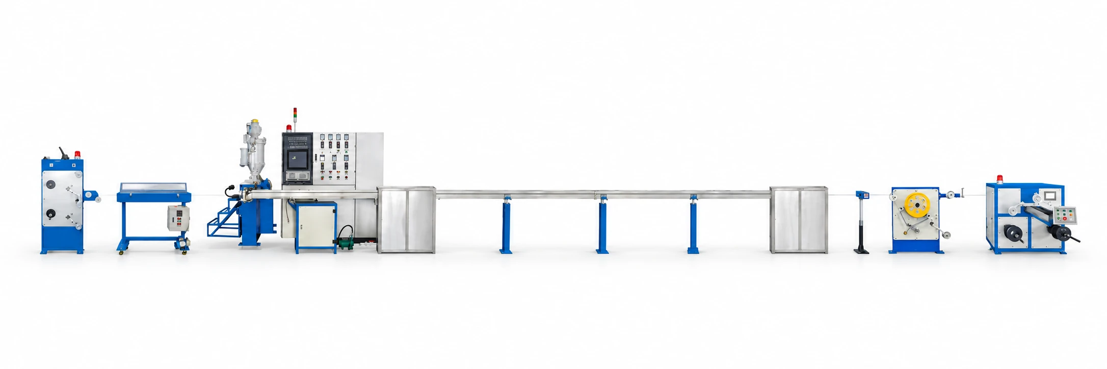

- HK-30 buffering and HK-50 simplex / duplex jacketing
- Verified cable structure, dimensions and fiber identification
- Optical and agreed mechanical release records

CABLE MACHINERY
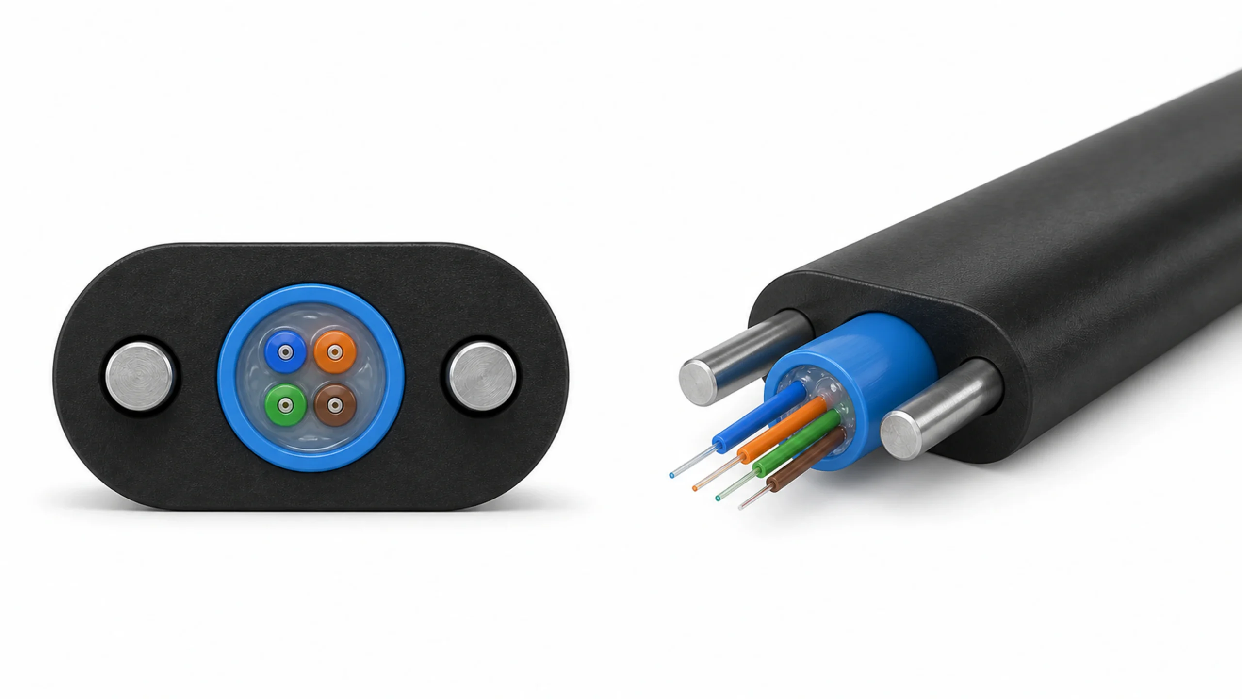
Thiết bị sản xuất cáp quang
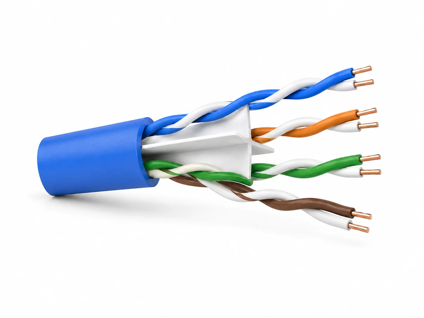
Thiết bị cho cáp xoắn đôi
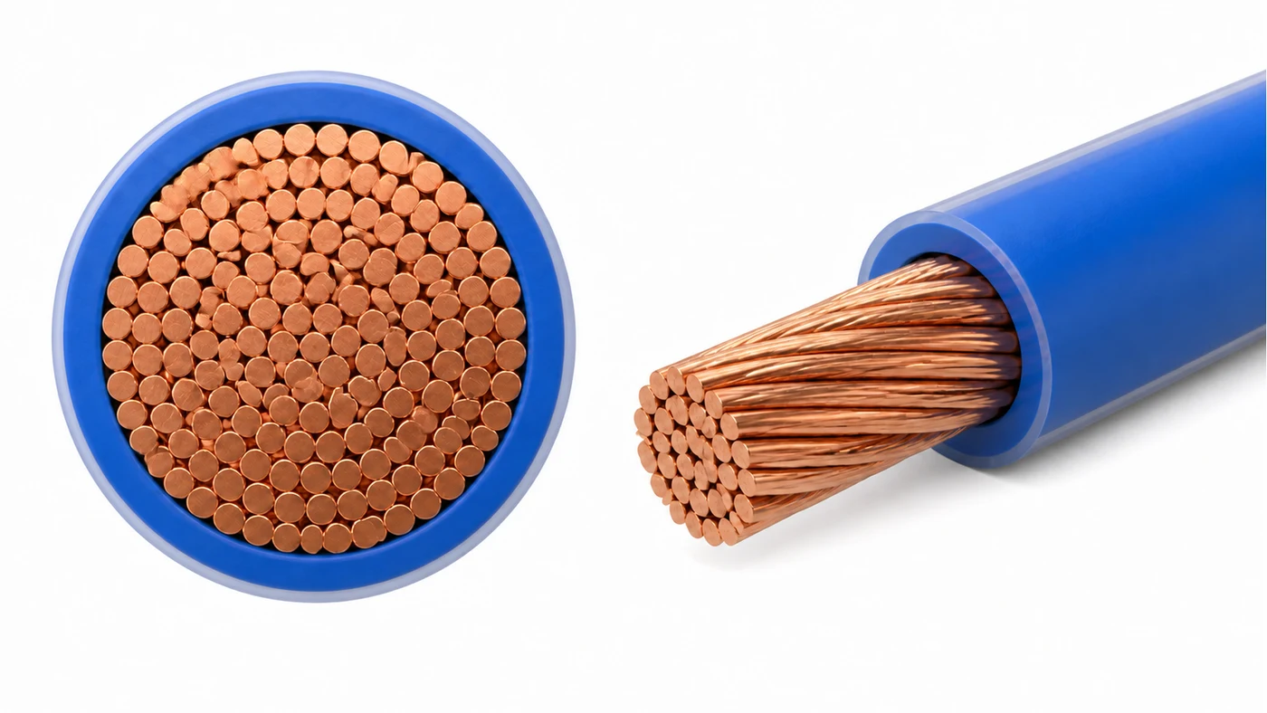
Máy móc cho dây và cáp điện có lớp cách điện
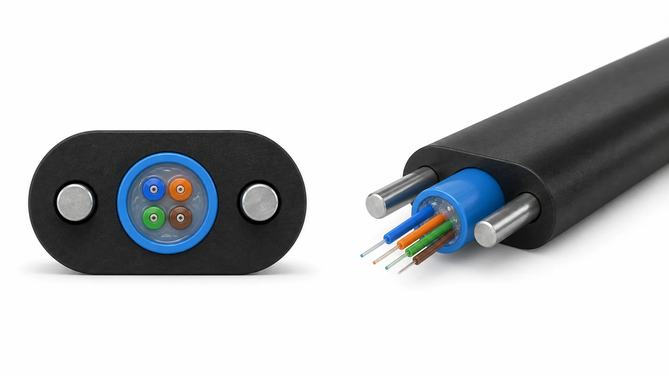
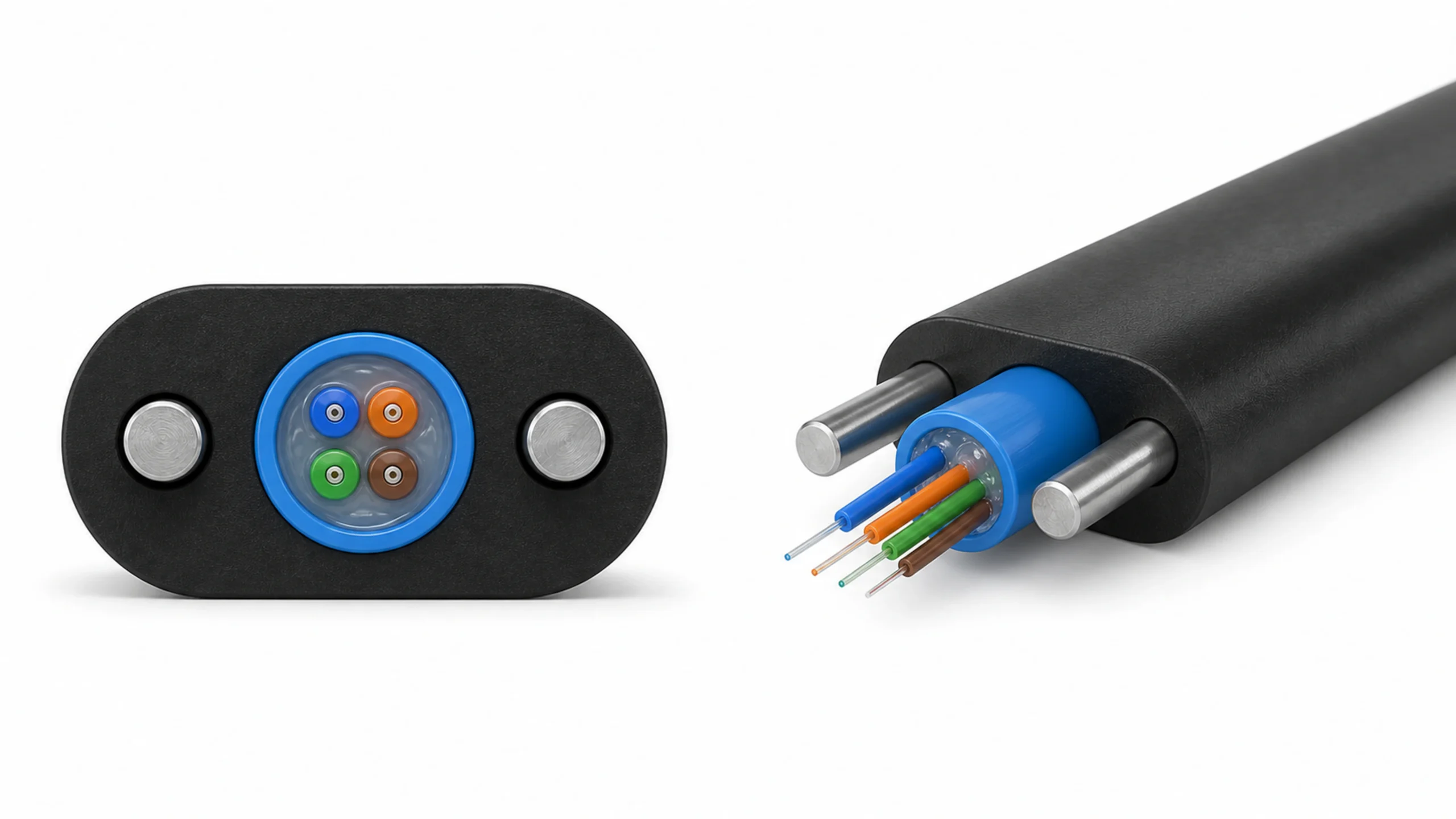
Duyệt các loại cáp quang
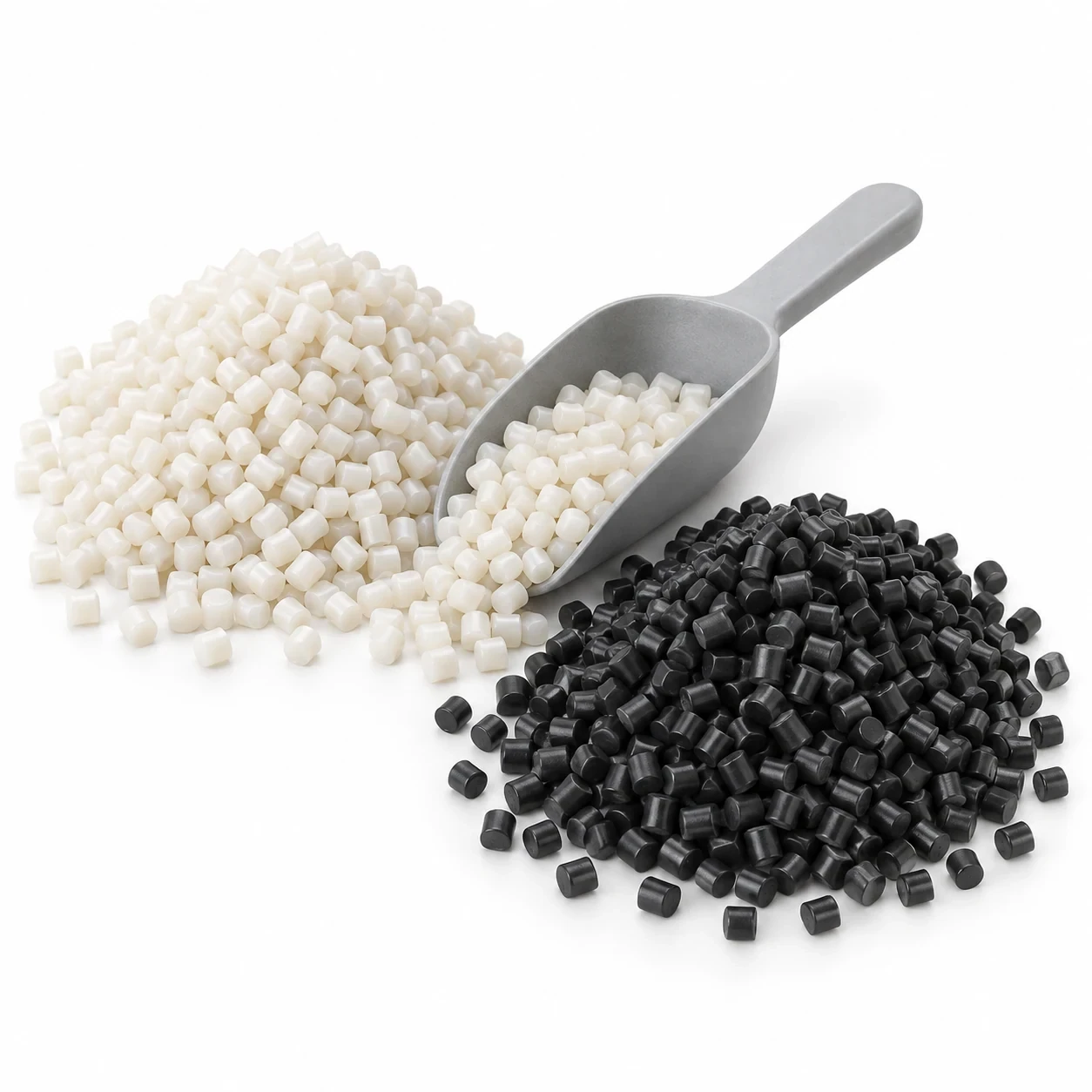
Vật liệu cho sản xuất cáp quang
Dây chuyền cáp hoàn chỉnh, vật liệu, bố trí và hỗ trợ khởi động.

Sản xuất cáp, lắp ráp MPO và kiểm tra quang học cuối cùng.
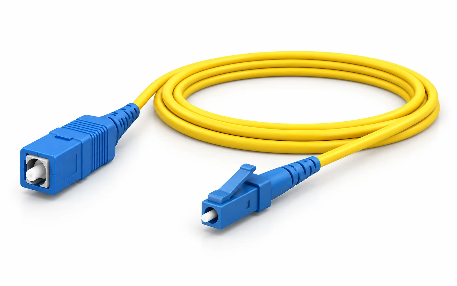
Cáp cơ sở, lắp ráp đầu nối, đánh bóng và xuất xưởng.
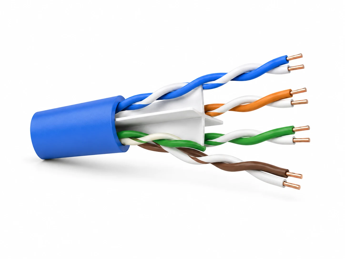
Lựa chọn thiết bị và lập kế hoạch quy trình cho cáp mạng.

01FIBER OPTIC PATCH CORD FACTORY SOLUTION
Từ sợi quang đến dây nhảy quang đã được kiểm tra.
Giải pháp nhà máy trọn gói bao gồm thiết bị, vật liệu, bố trí mặt bằng và bí quyết công nghệ cho sản xuất cáp và lắp ráp đầu nối chính xác.
Dành cho các nhà máy mới, các nhà sản xuất cáp hiện có và các doanh nghiệp lắp ráp sẵn sàng mở rộng.
Lên kế hoạch cho nhà máy của tôiKhám phá toàn bộ quy trình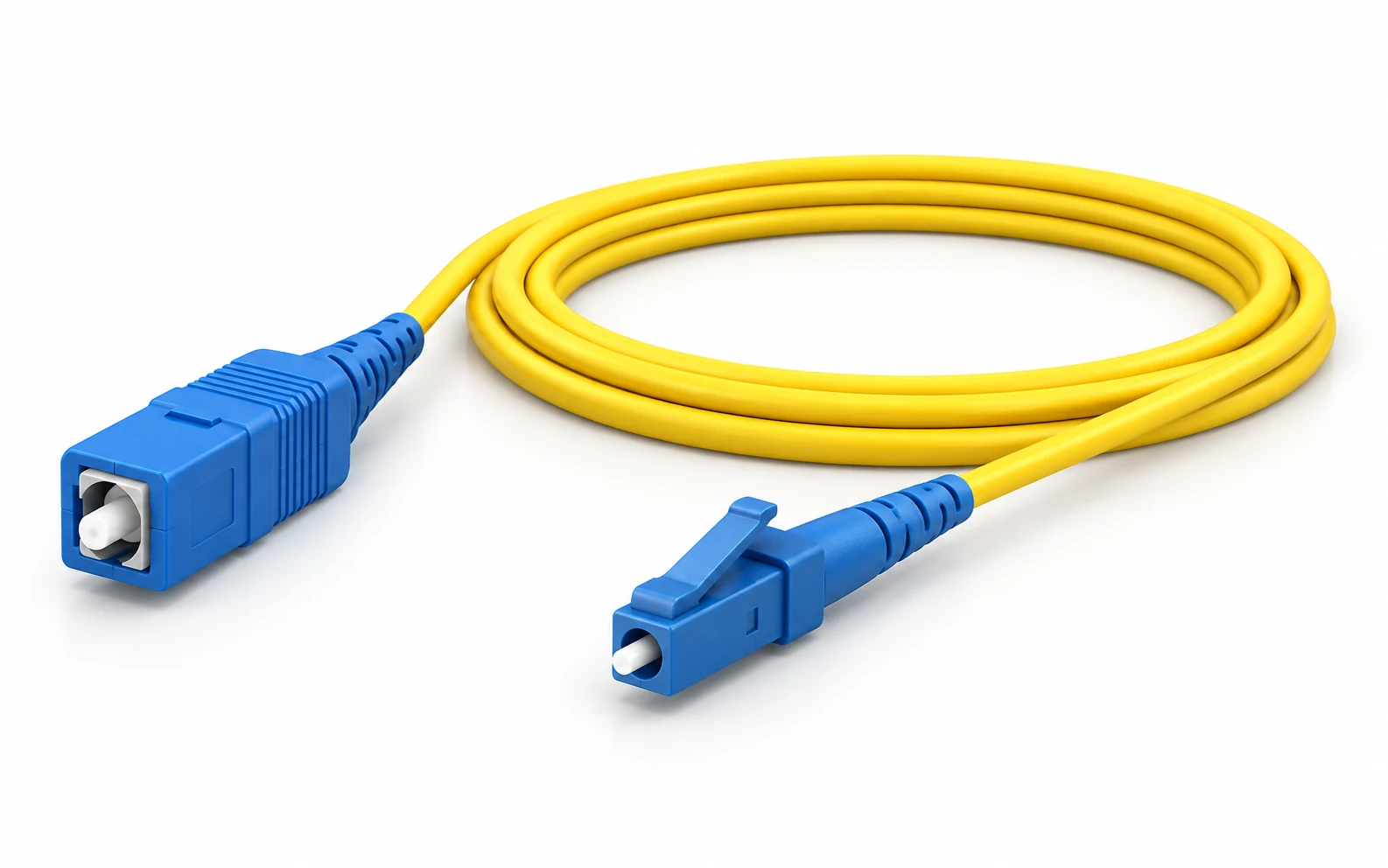
Illustrative reference.
Phạm vi cuối cùng tuân theo
approved product.
02INTERACTIVE PROCESS EXPLORER
Xem cần sản xuất những gì, các khu vực nào là bắt buộc và cách từng bước lắp ráp phù hợp trong một nhà máy sản xuất dây nhảy hoàn chỉnh.
STAGE 04 / 07
Cắt đoạn cáp đã được thả ra, nạp sẵn các bộ phận cần thiết và chuẩn bị từng đầu mà không làm hư hại sợi quang.
28 các hoạt động và điểm kiểm soát trải dài qua bảy giai đoạn. Mở một giai đoạn để xem toàn bộ phạm vi của nó.
Before production: approve the launch assembly, cable drawing, fiber category and count, connector families at both ends, polish, finished length, duplex mapping and acceptance plan. The signed work instruction controls the exact sequence.
Kiểm tra danh tính đầu vào, độ tương thích của lớp phủ và hợp chất, tình trạng quang học đầu vào và điều kiện lưu trữ.
Payoff → configured preparation → buffer extrusion → cooling → dimensional control → capstan and take-up. Identify each reel.
Đặt đầu vào đệm chặt, các bộ dẫn hướng, đầu ngang và dụng cụ cho quá trình kéo sợi đơn (simplex) hoặc kép (duplex) thực tế.
Verify yarn packages, paths and tension against the approved construction.
Chuẩn bị vật liệu → đùn lớp vỏ bọc → làm nguội → kiểm soát đường kính → kéo, tích trữ và thu cuộn. Liên kết tất cả các lô vật liệu.
Verify the actual cable structure, dimensions, surface and agreed optical results.
Các thử nghiệm cơ học và môi trường tuân theo thỏa thuận sản phẩm và kế hoạch lấy mẫu. Chúng tách biệt với việc kiểm tra đầu nối.
Xác nhận đầu nối, kiểu hoàn thiện, chiều dài thành phẩm, số lượng, nhãn mác và các phép thử. Liên kết cuộn dây hoặc lô cáp mua vào với lệnh sản xuất.
Bao gồm mức dung sai bóc vỏ/lắp ráp đã được phê duyệt và lưu giữ các số đo mẫu thực tế.
Luồn các đầu bịt, ống bọc và các chi tiết cố định khác cần thiết vào cáp trước khi thực hiện các bước tiếp theo để tránh mất khả năng tiếp cận. Tuân thủ thứ tự cụ thể theo từng loại đầu nối.
Control exposed length and preserve reinforcement and buffered fiber.
Expose the specified fiber length with a compatible tool and inspect for residue, scratches or breakage.
Use the approved cleaning method, protect the bare fiber and retain piece identity.
Kiểm soát danh tính vật liệu, quá trình chuẩn bị, thời hạn sử dụng và việc loại bỏ không khí theo hướng dẫn của nhà cung cấp.
Sử dụng kim, liều lượng và phương pháp xác minh đã được chỉ định; liên kết lô hàng với cụm lắp ráp.
Luồn sợi quang đơn vào đầu nối tròn của nó. Lắp ráp phần cứng theo trình tự đã được phê duyệt và xác nhận vị trí lắp đặt.
Sử dụng bộ khuôn được chỉ định và giữ nguyên bố trí aramid/bốt đã được phê duyệt. Vị trí chính xác trên tuyến đường phụ thuộc vào đầu nối.
Sử dụng các đầu giữ tương thích và chu kỳ thời gian-nhiệt độ đạt chuẩn; lưu giữ hồ sơ về tải trọng, chu kỳ và người vận hành.
Sau chuỗi trình tự lưu hóa và làm nguội đã được phê duyệt, hãy sử dụng dụng cụ vạch dấu đã chỉ định mà không làm sứt mẻ đầu nối. Thao tác bằng dụng cụ cầm tay không phải là máy móc có động cơ bổ sung.
Verify the SC / LC fixture and the qualified UPC / APC process. Include FC / ST only after variant review.
Kiểm soát màng phim, miếng đệm, tải trọng, thời gian và vệ sinh giữa các giai đoạn. Lưu giữ hồ sơ vật tư tiêu hao và đồ gá.
Sử dụng các vật tư làm sạch tương thích và giữ bề mặt đã hoàn thiện được bảo vệ khỏi tái nhiễm bẩn.
Use the correct adapter and agreed criteria. Clean and re-inspect contamination; route damage to controlled disposition.
Thỏa thuận riêng biệt về các thuộc tính đầu nối, thiết bị, giới hạn và kế hoạch lấy mẫu hoặc kiểm tra toàn bộ.
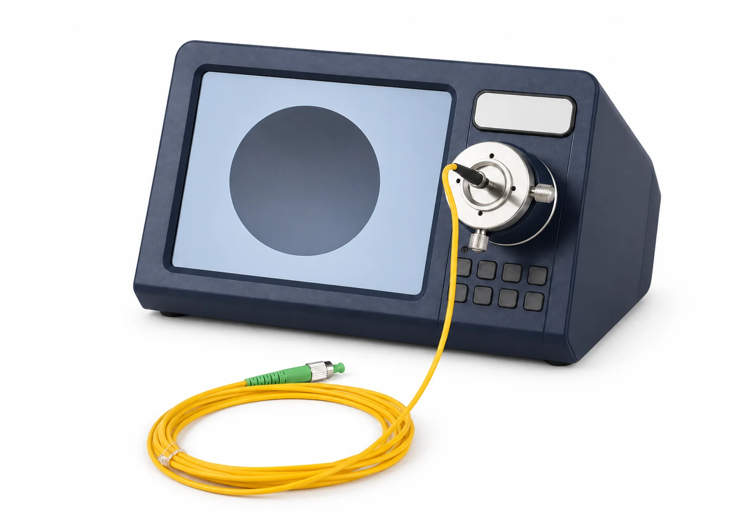
Xác nhận loại sợi quang, bước sóng, dây tham chiếu, bộ chuyển đổi, phương pháp, hướng và giới hạn trước khi kiểm tra. Liên kết kết quả thô với dây nhảy.
Check end identification and the ordered A/B fiber relationship. A single-fiber assembly does not need an MPO channel-map test.
Inspect housing, boot, retention and appearance against the control plan. A visual fault locator is supplementary, not an IL / RL replacement.
Lắp các nắp bảo vệ sạch, giữ nguyên điều kiện uốn đã thỏa thuận, dán nhãn cho cụm lắp ráp và lưu giữ hồ sơ nguồn gốc, linh kiện và kiểm tra của nó.
Segregate failed assemblies. Clean and re-inspect contamination; repolish or reassemble only within the approved connector limits. Repeat the affected inspection and optical checks, retaining both original and repeat results. Do not pass a damaged fiber by changing the test limit.
03COMPLETE FACTORY FLOW
Khu vực sản xuất và lắp ráp riêng biệt.
Clear release points. Connected production records.
Manufacture and release the patch-cord base cable.
Hoàn thiện, kiểm tra và xuất xưởng các cụm dây nhảy đã hoàn chỉnh.
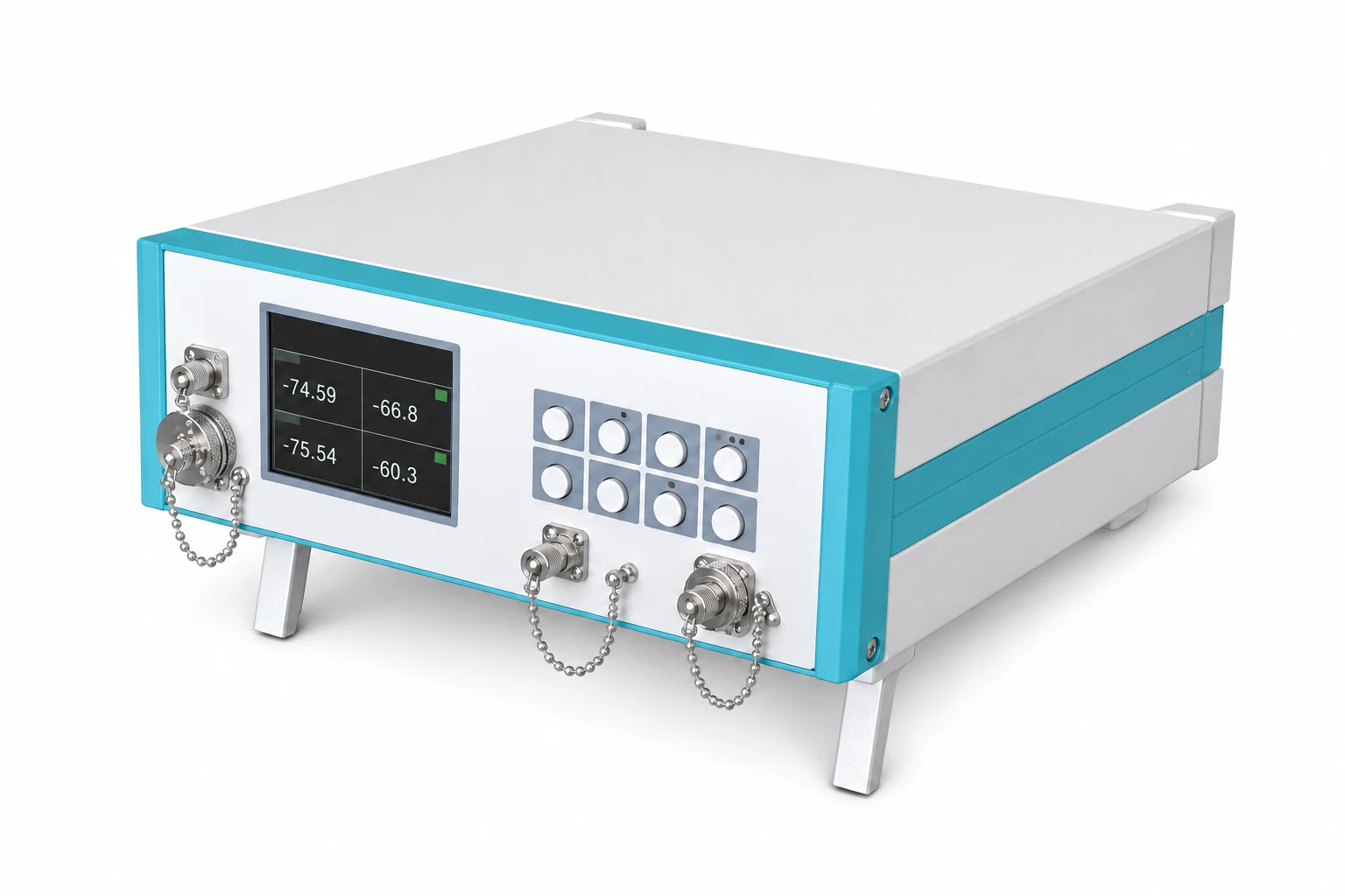
Một danh tính lắp ráp. Keep the link from input fiber reel to finished cable reel, cut length, component lots, connector ends, cure and polishing recipe, inspection images and optical results.
Lưu giữ hồ sơ về các sản phẩm lỗi và đã được sửa chữa lại. Việc kiểm tra quang học đạt yêu cầu không thay thế được bằng chứng nghiệm thu riêng của cáp gốc.
04PROJECT REQUIREMENT SNAPSHOT
Quyết định đầu tiên là cụm lắp ráp khởi động của bạn. Nó xác định cấu trúc cáp, các ô làm việc đầu nối và bằng chứng cần thiết để phê duyệt.
Build your project briefThis route covers conventional SC / LC epoxy-and-polish assemblies. FC / ST are project-specific fixture variants; MPO needs its own production route.
05EQUIPMENT BY PRODUCTION STAGE
Các dây chuyền cáp hoàn chỉnh, dụng cụ lắp ráp chuyên dụng và các thiết bị tháo rời riêng biệt.
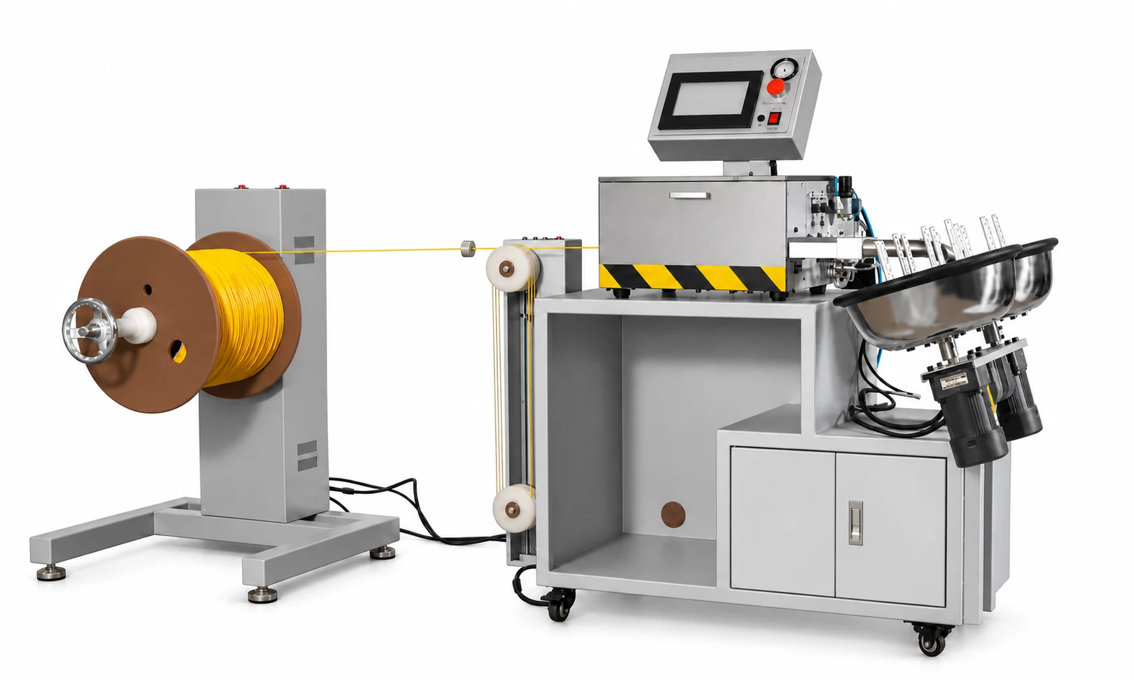
Hệ thống xả sợi có điều khiển, đùn lớp đệm, làm nguội, đo kích thước, cụm kéo sợi và thu cuộn tạo thành một dây chuyền sản xuất hoàn chỉnh.
Một dây chuyền riêng biệt và hoàn chỉnh áp dụng lớp gia cường aramid và lớp vỏ bọc ngoài lên đầu vào tight-buffered đã được phê duyệt. Khớp bộ dụng cụ simplex hoặc duplex với bản vẽ cáp.
Tên thiết bị mở ra trang dây chuyền sản xuất hoặc hướng dẫn quy trình thiết bị tương ứng. Chọn một hình ảnh để xem ghi chú về phạm vi và tiêu chí chấp nhận. Các trạm minh họa yêu cầu đồ gá và phụ kiện phù hợp với sản phẩm. Hình ảnh thiết bị chỉ mang tính chất tham khảo cấu hình, không phải là biên bản giao hàng cho khách hàng.
06RAW MATERIALS & INITIAL BOM SUPPORT
Lên kế hoạch đồng bộ cho đầu vào cáp, các thành phần đầu nối và vật tư tiêu hao trong quá trình sản xuất, để lô sản xuất đầu tiên có đầy đủ lộ trình vật liệu.
Xác định sợi, lớp gia cường và các hợp chất trước khi chọn cấu hình cuối cùng để sản xuất cáp.
Khám phá vật liệu cáp
Danh mục, khả năng tương thích lớp phủ, tình trạng đầu vào và mã cuộn.
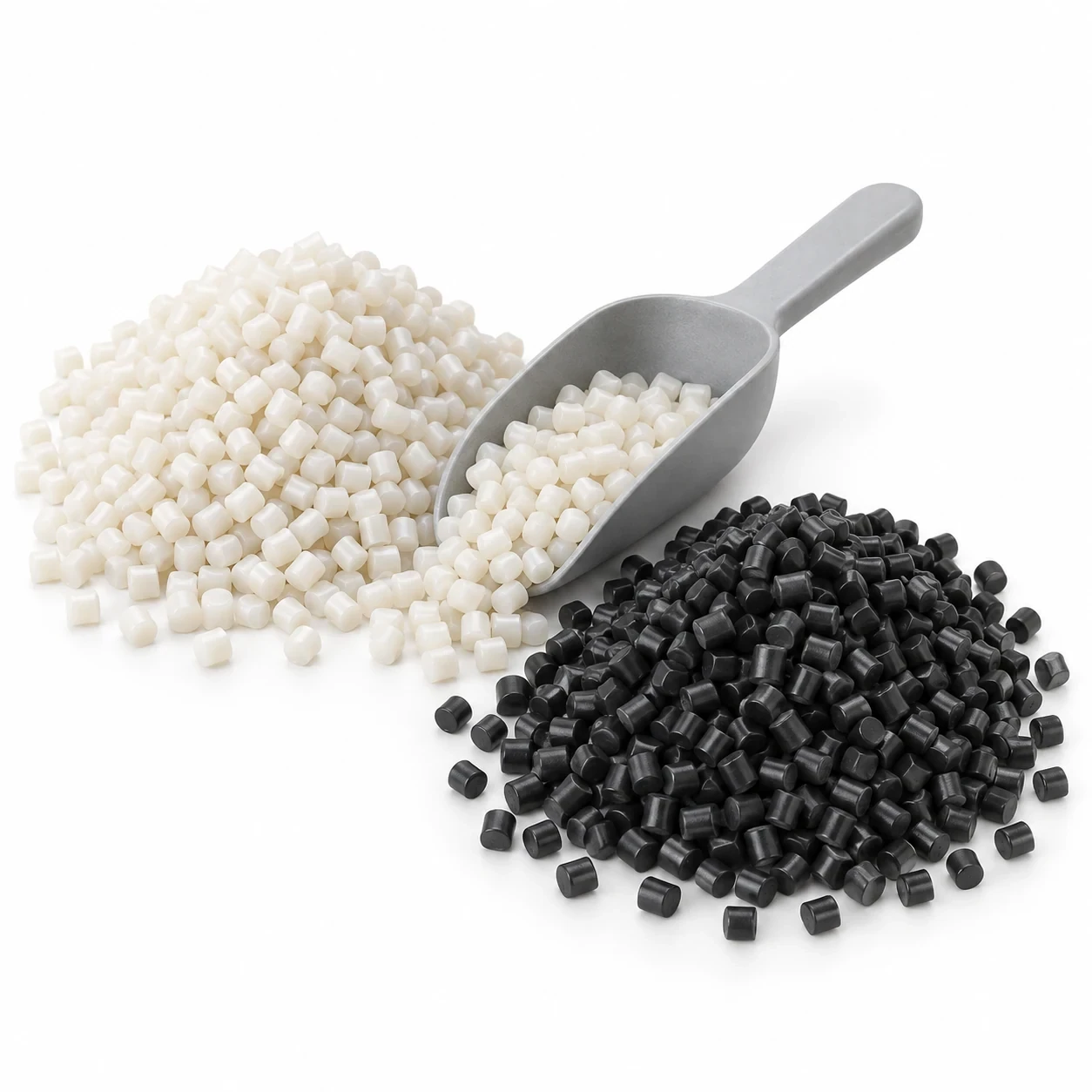
Separate material grades, drying, processing and storage instructions.

Construction, linear density, reel package and controlled application.
Tài liệu minh họa mang tính tham khảo. Các chi tiết, mác vật liệu và vật tư tiêu hao chính xác tuân theo sản phẩm và quy trình đã được phê duyệt.
Cable drawing, initial material BOM, supplier matching and trial-run material quantities.
07FACTORY LAYOUT & UTILITIES
Kết nối luồng vật liệu. Tách biệt công việc sản xuất cáp nặng với lắp ráp đầu nối chính xác.
Plan machine lengths, service access, reel routes, lifting and safe aisles around the confirmed equipment.

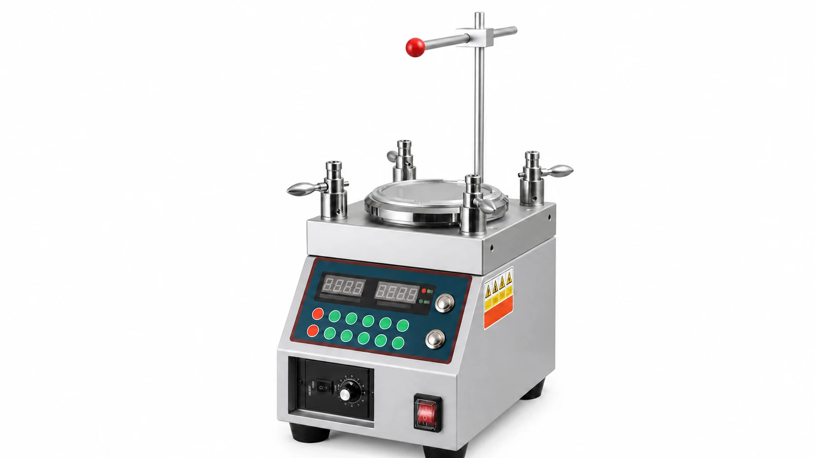
Xác định độ sạch, thao tác xử lý, yêu cầu về ESD (nếu áp dụng) và điều kiện lưu trữ từ quy trình đã chọn. Không mặc định bất kỳ cấp độ phòng sạch chung nào.
Voltage, frequency, connected loads and protection.
Làm mát dây chuyền, chất lượng nước và tuần hoàn nước.
Compressed air, ventilation and process-specific extraction.
Trạm làm việc, nhãn, hồ sơ và lưu trữ tệp kết quả.
A final layout follows your building dimensions, selected machinery and safety review. These workflow zones are not a construction drawing.
08PHASED FACTORY CONFIGURATION
A complete factory can be planned in phases. Keep one approved launch product and a clear acceptance boundary at each step.
Plan HK-30 tight buffering, HK-50 cable manufacture and the complete conventional connector-assembly route together.
Bắt đầu từ sợi quang mua sẵn. Xác nhận tất cả các giao diện và trách nhiệm nghiệm thu trước khi báo giá.
Lên kế hoạch cho nhà máy của tôi09PROJECT SCOPE & RESPONSIBILITY
HONGKAI engineers the cable-making route and coordinates specialist patch-cord assembly, inspection and test equipment. The signed scope defines who supplies, proves and supports each part.
10EXECUTION, FAT & HANDOVER
Các cột mốc được thống nhất sau khi xem xét phạm vi. Mỗi bước đều có một quyết định và một sản phẩm bàn giao, chứ không phải là cam kết chung chung về thời gian dẫn trước.
Launch product, connector specification, target output and acceptance plan.
Các dây chuyền được ghép nối, ô làm việc, BOM, bố trí mặt bằng và ma trận trách nhiệm.
Chạy tuyến đường đã mua tại FAT và lưu giữ bằng chứng liên quan.
Kiểm tra độ sẵn sàng của hiện trường, lắp đặt và nghiệm thu phạm vi đã xác định.
Đào tạo người vận hành, lặp lại các kiểm tra đã thống nhất và đóng các mục đang mở.
Theo dõi một cụm phóng đã được xác định từ cuộn cáp nguồn đến kết quả quang học cuối cùng của nó. Bao gồm nghiệm thu ở giai đoạn cáp và nghiệm thu cuối dây chuyền trong cùng một kế hoạch dự án.
Đọc hướng dẫn quy trình đầy đủCable drawing, connector system, connector specification and test limits.
Cable results, cure record, end-face images, geometry when specified and optical test files.
Repeatable work instructions, recipe control, cleaning, test setup and permitted rework.
Request an agreed sample run and evidence package for the scope you are purchasing.
Images on this page are presentation references. They are not a claim that a specific customer factory has been delivered.
11KNOWLEDGE & DECISION SUPPORT
Tuân theo tuyến đường, các điểm kiểm soát và bằng chứng giải phóng.
Understand the two cable-manufacturing phases.
Match input materials to the approved construction.
12FREQUENTLY ASKED QUESTIONS
Answers to the questions that change a project’s scope.
Toàn bộ quy trình bao gồm đệm chặt, sản xuất cáp simplex/duplex, tháo cáp, lắp đầu nối, đánh bóng, kiểm tra và thử nghiệm quang học. Phạm vi dự án đã ký xác định rõ các phần nào được cung cấp và các phần nào do bên mua tự cung cấp.
Đúng vậy. Cáp mua đủ tiêu chuẩn có thể phục vụ cho quy trình lắp ráp trước. HK-50 có thể được bổ sung khi bạn mua sợi quang có lớp đệm chặt, và HK-30 có thể đưa quá trình tạo lớp đệm vào nội bộ. Mỗi giai đoạn vẫn cần có hồ sơ phê duyệt đầu vào và hồ sơ phát hành riêng biệt.
SC và LC là các phạm vi chính theo phương pháp truyền thống dùng keo epoxy và đánh bóng. FC và ST có thể được xem xét như các biến thể về đồ gá và dụng cụ. Hệ thống đầu nối, kết cấu cáp và lớp hoàn thiện phải được phê duyệt cho từng sản phẩm ra mắt.
Các cụm MPO đa sợi cần ống lót được ghép nối riêng biệt, cùng với quy trình chuẩn bị, đánh bóng, kiểm tra, ánh xạ và phạm vi thử nghiệm riêng. Hãy sử dụng giải pháp nhà máy MPO riêng biệt cho dự án đó.
Đừng giả định điều đó. Hãy khớp đầu nối, hình học ống lót, đồ gá, màng phim và công thức với độ hoàn thiện đã được chỉ định. Tên máy móc alone không chứng minh khả năng hỗ trợ mọi loại đầu nối hoặc phương pháp đánh bóng.
Xác định loại sợi quang, bước sóng, phương pháp tham chiếu, hướng kiểm tra, bộ chuyển đổi, dây cáp tham chiếu, giới hạn chấp nhận và bên chịu trách nhiệm hiệu chuẩn. Lưu giữ kết quả theo định danh của cụm lắp ráp. Kiểm tra ánh xạ duplex khi áp dụng.
HONGKAI supplies its defined cable-making scope and integrates specialist back-end equipment. The proposal separates HONGKAI-manufactured, specialist-integrated and buyer-supplied items, including training and after-sales responsibility.
Start with launch connector pairs, simplex or duplex construction, fiber category, UPC / APC finish, length range and output targets. Add factory country, shifts, available floor space, utilities and existing equipment. Undecided fields can be reviewed during engineering.
13YOUR PATCH CORD FACTORY PROJECT
Build a project brief around your patch-cord product, production target and site. Leave undecided specifications open for engineering review.
Review your brief before sending it to HONGKAI. Nothing is sent automatically.
Bản vẽ cáp, thông số kỹ thuật đầu nối và mặt bằng nhà xưởng của bạn. Bạn có thể chia sẻ những tài liệu này trong buổi trao đổi kỹ thuật tiếp theo.
 English English
  Русский
 हिन्दी
 한국어
한국어
 বাংলা
বাংলা
 Bahasa Indonesia
 Tiếng Việt
 മലയാളം
 Português do Brasil
 العربية
 فارسی
فارسی