










A network-cable factory can make a reel that passes one handheld test and still lack the evidence needed to release Cat6 product consistently. Factory owners, production managers and technical buyers therefore need to decide what is being accepted: a cable design, a production lot, a third-party product listing, or an installed link.
Cat6 compliance is proved by a connected evidence chain, not by a generic “TIA certificate.” Start with the current contract standard and exact cable construction, control the geometry that creates transmission performance, test the finished cable with suitable laboratory methods, and keep lot-level records. Treat installed-link testing and independent product verification as separate evidence layers.
A distinção é importante antes que a maquinaria seja encomendada. Um completo Rota de produção de cabo LAN must connect conductor preparation, insulation, pair twisting, cabling, optional shielding, sheathing, testing and packing. The test plan must be designed with that route because end-of-line testing can identify a result; it cannot repair uncontrolled conductor, insulation or pair geometry.
Substitua “Certificação TIA” por um Objeto de Aceitação Nomeado
ANSI/TIA-568.2-E is a balanced twisted-pair cabling and components standard, not a universal certificate issued to every Cat6 cable factory. A buyer should name the standard edition, product construction, verification body if any, sample scope and evidence required instead of asking only for “TIA certification.”
TIA announced ANSI/TIA-568.2-E in November 2024 as the revision of ANSI/TIA-568.2-D.1 TIA also explains that its engineering committees develop standards through an ANSI-accredited process.2 Esses fatos estabelecem o papel das normas. Eles não estabelecem que a TIA tenha inspecionado uma fábrica, testado um carretel ou certificado um produto Cat6.
A frase “aprovação Cat6” pode esconder quatro solicitações diferentes:

AI-generated explanatory illustration. Match each acceptance object to its own evidence; this is not a certificate, test result or installation drawing. View full-size illustration.
| Acceptance object | Main question | Appropriate evidence | What it does not prove alone |
|---|---|---|---|
| Cable design | Does the defined cable construction meet the signed electrical and physical requirements? | Controlled specification, qualified samples, laboratory results and change control | That every later production lot remains within control |
| Production lot or reel | Was this identified output released against the factory plan? | Traceable raw-material, process, dimensional and finished-cable records | Independent product verification or installed-link performance |
| Independent product verification | Did a named third party assess the identified product against a named specification? | Current directory entry or certificate with product, standard edition, scope and surveillance status | A different model, construction, jacket rating or unlisted factory |
| Link ou canal permanente instalado | Does the completed cabling system pass the project’s field limits? | Calibrated field-test report with link type, adapters, instrument and results | Factory cable qualification without the rest of the installed system |
Intertek’s ETL Verified cabling directory illustrates the third-party layer: entries are organized by company and specific product, while a certificate identifies the tested construction and referenced standard.3 One published certificate also states that verification of transmission requirements is distinct from a certification program.4 This is why a buyer should verify the exact wording, product identity, current status and surveillance arrangement rather than treating any logo as a broad Cat6 claim.
Decision criterion: Write the acceptance object as a noun before choosing the test: “bulk horizontal cable,” “patch cord,” “production reel,” “permanent link” or “channel.” If the noun changes, the fixture, limits, sample preparation and responsible party may also change.
Freeze the Cable Construction Before Selecting Tests
A Cat6 test plan begins with the saleable cable definition. Category alone is incomplete because conductor, pair, separator, shielding, jacket, installation use and delivery form change what must be manufactured and what evidence the customer may request.
The buyer should approve at least these inputs before the supplier fixes the equipment route or FAT scope:
- solid or stranded conductor and the approved conductor material;
- conductor size and finished conductor tolerance;
- insulation material, nominal dimensions and color identification;
- U/UTP, F/UTP or another defined screening construction;
- pair lay plan and any separator construction;
- cabling lay, binder or shield elements where applicable;
- jacket material, marking, color and market-specific fire or environmental requirement;
- bulk cable, patch cord, permanent-link or channel acceptance boundary;
- edição padrão alvo, especificação do cliente e programa de terceiros, se necessário;
- reel or box length, sample length, conditioning and release sampling plan.
IEC 61156-5:2020 is a separate official reference for symmetrical pair/quad cables used primarily in horizontal floor wiring. Its public scope covers individually screened, common-screened and unscreened pairs or quads; the purchased standard is needed to establish the applicable detailed requirements.5 ISO/IEC 11801-1:2017, with its later amendment, addresses generic customer-premises cabling across multi-vendor systems.6 These standards are related to the product and system decision, but they are not interchangeable labels. The signed order must say which document and edition governs each acceptance object.
Common mistakes: A quotation says only “Cat6 UTP, Fluke test pass.” It does not identify bulk cable versus installed link, conductor construction, sample preparation, test method, standard edition, parameter set, limit set, instrument class or raw-data format.
Desempenho de Construção a Montante do Analisador Final
Cat6 electrical performance is created through repeatable conductor, insulation, twisting and cabling geometry. Final transmission testing verifies the result, while upstream process records explain why the result is stable or why it failed.
Para uma rota Cat6 UTP, o plano de controle mais útil segue o processo físico:
| Fase de produção | Evidência do processo a reter | Por que o registro pertence à cadeia de prova |
|---|---|---|
| Preparação do condutor | Lote do fornecedor, identidade do material, dimensão do condutor e dados aplicáveis de resistência | Estabelece a entrada elétrica e dimensional para a isolação |
| Isolamento do condutor interno | Lote de isolamento, tendência de diâmetro, evidência de excentricidade ou concentricidade, condição da superfície, registro do teste de centelhamento e identificação da bobina | Acompanha a geometria e a integridade de cada condutor isolado |
| Torção de pares | Identidade do par, configuração de passo, configurações de tensão/torção reversa quando aplicável, mapeamento da bobina e condição visual | Conecta o equilíbrio do par e a repetibilidade ao resultado final do cabo |
| Cabeamento e separador | Sequência de pares, passo do cabo, identidade do separador, configurações de tensão e observações de deformação | Registra a geometria criada quando quatro pares se tornam um núcleo de cabo |
| Revestimento | Lote da cobertura, dimensões do núcleo pré-cobertura, tendência do diâmetro final, registro de marcação/comprimento e bobina de enrolamento | Indica se o processo final alterou o núcleo ou a identidade do produto |
| Teste laboratorial de cabo acabado | ID da amostra, comprimento, condicionamento, fixação, status de calibração, conjunto de padrão/limite, gráficos brutos e resultado | Fornece a evidência de liberação para a amostra e o lote identificados |
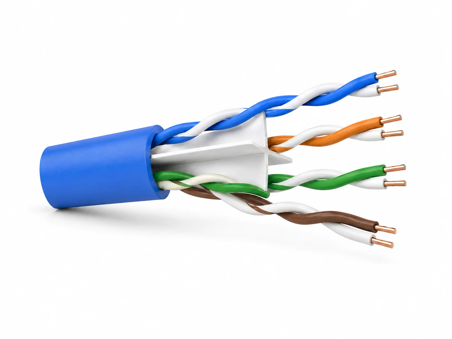
The HONGKAI LAN cable production guide maps Cat6 UTP production through insulation, precision pair twisting, separator handling where the approved construction requires it, cabling, sheathing, electrical testing and packing. That route is a project reference, not a declaration that every Cat6 design uses the same separator, machine model or acceptance limit.
How to verify: Ask the line supplier to map each critical finished-cable result back to a controllable production variable and a retained record. “The analyzer will tell us” is incomplete unless the factory can identify which process data will be checked after a failure.
Separar testes de laboratório da fábrica de testes de campo
Factory cable release and installed-cabling field testing answer different questions. A field tester is valuable for permanent-link or channel acceptance, but it should not automatically replace the laboratory method and fixtures needed to qualify bulk cable or components.
TIA’s ANSI/TIA-1152-A announcement defines requirements for field test instruments used with balanced twisted-pair cabling, including reporting and accuracy performance.7 That scope is useful when the acceptance object is an installed cabling configuration. A factory product program may require different laboratory instrumentation, fixtures and sample preparation to assess the cable or component itself under the governing product standard.
Use uma escada de evidências em vez de um único item genérico de testador:
| Evidence layer | Typical decision | Categoria de instrumento ou registro | Buyer check |
|---|---|---|---|
| Controle em processo | O processo de fabricação está mantendo a geometria aprovada? | Medição de diâmetro/concentricidade, teste de centelha, registros de passo/tensão e inspeção dimensional | Cada leitura pode ser associada a um núcleo, par, carretel e janela de tempo? |
| Liberação elétrica da fábrica | A amostra de cabo identificada atende aos requisitos do cabo assinado? | Sistema adequado de medição de resistência e transmissão com acessórios e software aprovados | Os métodos, calibração, comprimento da amostra, condicionamento e gráficos brutos são registrados? |
| Independent verification | O produto identificado foi avaliado pelo organismo nomeado? | Relatório de terceiros, entrada em diretório e evidência de vigilância | A empresa, fábrica, modelo, construção e edição padrão coincidem? |
| Installation acceptance | O enlace ou canal concluído atende ao limite do projeto? | Testador de campo e adaptadores corretos de enlace/canal | O conjunto de limite selecionado está correto para a configuração instalada? |
For machinery procurement, the HONGKAI LAN production guide identifies electrical testing as a supporting system whose scope requires written project confirmation. The buyer should separately name responsibility for the analyzer, fixtures, software, calibration service and third-party verification; those items should not be implied by the extruder, twister or cabling machine.
Note: A field PASS file is evidence for the tested configuration at the recorded time. It is not by itself evidence that every reel from the factory, every product variation or every future production lot meets the same requirements.
Fluke Testing: Is the Requirement for a 305 m Reel or a 100 m Connection?
Before accepting a requirement to “pass Fluke,” define the product being tested, its actual test length, the connection arrangement and the selected limit. A 305 m box or reel and a connection of approximately 100 m represent different customer requirements; a PASS result is useful only when the test setup matches the agreed acceptance object.
HONGKAI insight: In the customer requirements described for this guide, Fluke testing is a preferred practical acceptance reference. Some customers ask about a complete 305 m box or reel; others describe a finished connection of around 100 m. Confirm which form the customer means before discussing performance or a pass rate. These are examples of project requirements, not a universal length rule or a promised test outcome.
Use precise terms when converting the customer’s wording into the test plan. Fluke describes a conventional channel as the complete connection including patch and equipment cords, with an overall length limit of 100 m. A permanent link is the fixed portion, with a 90 m limit in that model. Testing a patch cord itself uses the relevant patch-cord limits and adapters, which assess its end connections differently from channel testing.8 Somente o comprimento, portanto, não identifica o modo de teste correto.
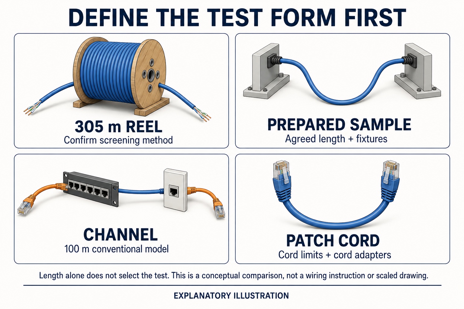
AI-generated conceptual comparison, not a wiring diagram. The 100 m figure refers to the conventional channel model, including its cords. Reel screening, prepared-sample testing and patch-cord testing require their own agreed methods and limits. View full-size illustration.
| Customer wording | O que o comprador deve esclarecer | Registre antes de aceitar o resultado |
|---|---|---|
| “Test the 305 m box or reel” | É necessário testar o cabo enquanto estiver enrolado ou qualificar uma amostra preparada conforme os requisitos dos componentes? Ambas as extremidades estão acessíveis? | Embalagem e comprimento testado, condição em carretel/desenrolado, configuração de extremidade única/dupla, parâmetros medidos e limite acordado |
| “Test the approximately 100 m finished connection” | Trata-se de um canal, de uma amostra de cabo preparada ou de outra disposição específica de ponta a ponta? | Desenho de conexão, comprimento real, conectores/tomadas, adaptadores e nome exato do limite |
| “Teste o cabo de derivação” | O cliente quer dizer o cabo como um componente, incluindo seus conectores, ou um canal completo contendo esse cabo? | Construção e comprimento do cabo, configuração aplicável do teste do cabo e critérios de aceitação |
Fluke’s single-ended DSX application note explains that reel screening measures a limited parameter set and cannot replace all double-ended measurements. It also notes that coiling can affect results and distinguishes typical 305 m reels from formal component testing based on a prepared 100 m sample with specified terminations.9 Confirm the supported method with the instrument supplier; do not select a channel limit merely to obtain a PASS for a reel.
Evidence to request: Save the Fluke model, software version, adapter identification, calibration status, test-limit name, cable/sample ID, actual length and complete result file. If the customer requests a pass rate, agree whether the denominator is boxes, reels, prepared samples or finished connections, and how first tests and retests are reported. Keep differently configured tests in separate result groups; no acceptance percentage is assumed here.
Diagnosticar um resultado com falha através da cadeia de processo
A failed Cat6 result should trigger a controlled check sequence: first verify the sample and measurement setup, then inspect the production records connected to the failure pattern, and only then adjust the process. Changing several settings at once destroys the evidence needed to confirm the cause.
Use the table as a proposed investigation record, not a confirmed diagnosis or a list of the most common causes. Each process connection must be checked against the actual cable design, raw measurements and the factory’s validated process plan; the table does not replace the governing test method.
| Família de resultados observados | Verifique antes de alterar a produção | Áreas do processo a inspecionar em seguida | Recovery evidence |
|---|---|---|---|
| Resultado inesperado de atenuação ou perda por inserção | Comprimento da amostra, temperatura do condutor, conectores/dispositivo, calibração e normalização do comprimento | Registro da dimensão/material do condutor, emendas, condição da isolação e comprimento final | Resultado repetido da mesma amostra mais uma amostra de confirmação identificada separadamente |
| Irregularidade relacionada à perda de retorno ou impedância | Consistência de fixação, terminação, manipulação de amostras e traço bruto | Diâmetro do núcleo/concentricidade, estabilidade do passo do par, tensão de cablagem, posição do separador e deformação induzida pela cobertura | Stable raw trace and dimensional/process records within the approved window |
| Falha relacionada à diafonia | Pair identification, adapter mapping, fixture isolation and limit set | Coordenação do passo dos pares, equilíbrio dos pares, cruzamento/sequência, geometria do separador e deformação dos pares durante o encordoamento ou revestimento | Repeatable result across the approved sample plan with traceable pair/process data |
| Preocupação com resistência ou desequilíbrio de resistência | Contact resistance, sample preparation, instrument zeroing and temperature correction method | Entrada do condutor, tendência de diâmetro, emendas e identidade do par/núcleo | Corrected measurement plus conductor and sample traceability |
| Preocupação com atraso ou sincronização entre pares | Comprimento da amostra, mapeamento do par e configurações do software | Pair lay plan, actual lay records and pair length relationship | Identidade do par confirmada e medição repetível conforme o método assinado |
Red flags: The only retained record is a screenshot that says PASS. It omits the raw plot, test limit, standard edition, sample ID, instrument serial number, calibration state, adapter/fixture, operator and time.
Transforme a conformidade num pacote de RFQ e evidências FAT
The machinery RFQ should define who supplies each production and testing function, while FAT should prove the agreed sample can be produced under recorded conditions. Product verification and continuing factory surveillance remain separate commercial and conformity-assessment scopes.
Monte o pacote de RFQ com base nas seguintes entradas.
- the approved cable drawing and construction schedule;
- as edições das normas aplicáveis e os limites específicos do cliente;
- cada variante de produto comercializável incluída no escopo da primeira aceitação;
- the planned raw material and conductor supply condition;
- a rota do processo e o mapa de responsabilidade da máquina;
- required in-line gauges, spark testing and data retention;
- o conjunto de parâmetros do laboratório da fábrica, o dispositivo de fixação e a responsabilidade pelo software;
- comprimento da amostra, condicionamento, regras de terminação e repetição de testes;
- for Fluke-based acceptance, the box/reel, cable-sample, patch-cord or channel boundary, exact limit and pass-rate calculation;
- FAT material, sample plan, stable-run definition and witness responsibilities;
- alvo de verificação independente, proprietário da aplicação e limite de vigilância;
- limite de teste em campo se a aceitação da instalação também fizer parte do projeto;
- report format, raw-data export and traceability fields.
Evidence to request: For the first accepted Cat6 run, retain the material lots, machine setup, stable production window, reel map, dimensional data, sample extraction point, laboratory setup, raw results, disposition and any approved deviation in one release package.
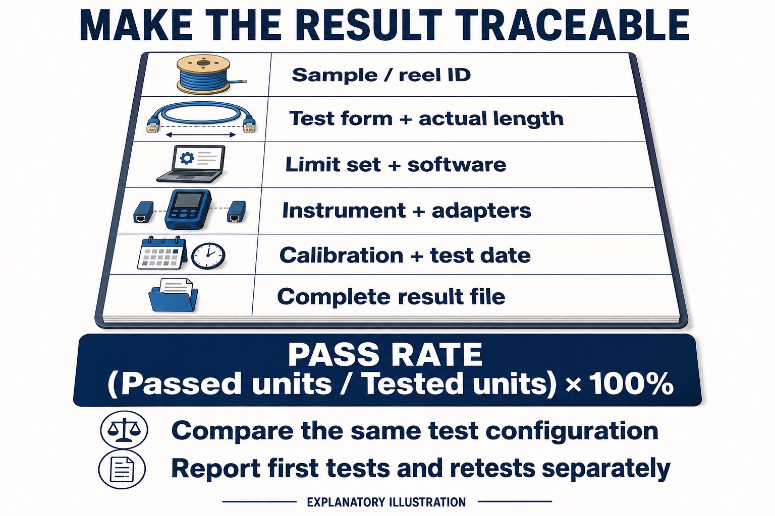
AI-generated explanatory illustration, not a real test report. Pass rate equals passed units divided by tested units, multiplied by 100%. Agree the unit, use the same test configuration within each result group, and report first tests and retests separately; no acceptance percentage is implied. View full-size illustration.
The factory should also protect change control. A different conductor, insulation grade, pair lay plan, separator, jacket compound, supplier, tooling or process window may affect the evidence basis. The responsible technical owner should decide whether the change needs a comparison trial, partial requalification, full third-party review or only a documented routine check.
The resulting release package should let the buyer trace an accepted sample back to the cable drawing, material lots, production window and test setup. Keep that evidence tied to the approved construction so a later product or process change receives an explicit technical review.
-
Comunicado TIA para ANSI/TIA-568.2-E, released in November 2024. ↩
-
Visão geral do desenvolvimento de padrões TIA, describing TIA engineering committees and the ANSI-accredited process. ↩
-
Diretório de produtos de cabos verificados pelo Intertek ETL, organizado por empresa listada e produto.↩
-
Exemplo de Certificado de Conformidade Verificado pelo Intertek ETL, used only to illustrate the scope wording of one independent verification document. ↩
-
IEC 61156-5:2020 official catalogue page, para cabos de fiação horizontal no piso com pares/quads simétricos.↩
-
Página oficial do catálogo ISO/IEC 11801-1:2017, incluindo o ciclo de vida da emenda e do corrigendum publicados. ↩
-
TIA announcement for ANSI/TIA-1152-A, descrevendo os requisitos para instrumentos e medições de teste em campo com pares trançados balanceados.↩
-
Explicação da Fluke Networks sobre testes de canal, enlace permanente e cabo de ligação, usado para a terminologia de configuração de teste; confirme a edição atual do contrato e a biblioteca de limites do instrumento para aceitação.↩
-
Fluke Networks: Teste de Extremidade Única com o Analisador de Cabos DSX, explicando os limites da triagem em carretéis e sua distinção em relação aos testes formais de componentes.↩

 English
  हिन्दी
  فارسی
فارسی