




A cable extrusion machine can appear large enough on a quotation and still leave the buyer with an unanswered question: which products can the complete line make at an agreed, repeatable rate? A screw diameter, a maximum output figure and a mechanical line-speed rating answer different parts of that question.
Size the extrusion stage around the required material, polymer mass per metre and product range. Then verify that the crosshead, cooling, haul-off, measurement and reel-handling equipment can support the same product at the agreed quality.
This guide concerns insulation or sheathing applied to an existing conductor or cable core. It does not size a compounding plant, set electrical installation requirements or promise a production rate for an unspecified compound. The useful purchasing result is a tested product envelope—not the largest number in a machinery table.
Start with a Product Envelope, Not a Screw Diameter
One representative cable rarely describes a factory’s entire requirement. A light coating at modest speed may demand very little polymer, while a thicker sheath at a lower speed can require more kilograms per hour. The smallest finished cable is therefore not automatically the lowest-output job, and the largest outside diameter is not automatically the highest-output job. Calculate the demand for each required product before selecting the trial cases.
Keep the input to this extrusion stage separate from the finished product. For insulation, the incoming object may be a solid or stranded conductor. For sheathing, it may already contain insulated cores, binders, shields or another sheath. Use the dimensions and construction of the object that actually passes through the crosshead, not a conductor designation copied from an earlier process.
Build a short product-envelope table from real drawings and orders. It should make the differences between products visible without turning a quotation into a catalogue of every possible cable.
For HONGKAI’s initial sizing review, the starting point is the cable the customer intends to make and the required production rate. The proposed extruder must then be checked against the relevant product-and-material operating range. A nominal main-machine size alone does not close that selection.1
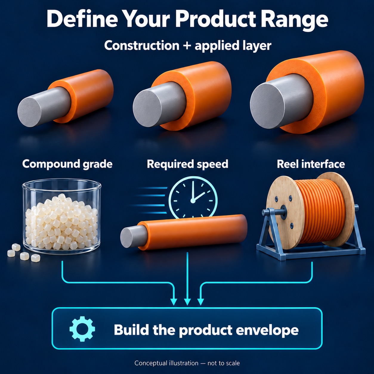
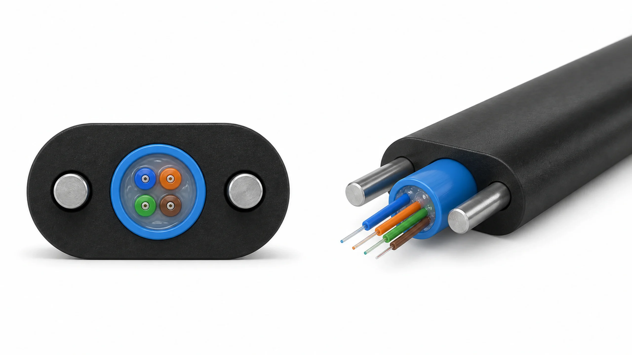
Conceptual illustration—not to scale. The grey cores are generic placeholders, not specified conductor constructions. Define the layer, compound, running target and reel interface together; outside diameter alone does not determine polymer demand.
| Product-envelope field | Record for each required product | What the comparison can reveal |
|---|---|---|
| Incoming construction | Actual incoming dimensions, shape and surface; drawing revision | A nominal conductor size does not define the crosshead input |
| Applied layer | Finished dimensions, minimum wall and permitted variation | Products with similar outside diameters may require different polymer mass |
| Compound | Supplier, grade and applicable processing information | Output evidence for one material is not evidence for every material family |
| Production target | Required running speed and planned order length | The relevant demand is the product-and-speed combination |
| Handling interface | Pay-off and take-up reel drawings, package weight and handling method | A suitable extruder can still be attached to unsuitable handling equipment |
| स्वीकृति आधार | Product specification, measurement method and required records | A speed figure is meaningful only when the accepted product is defined |
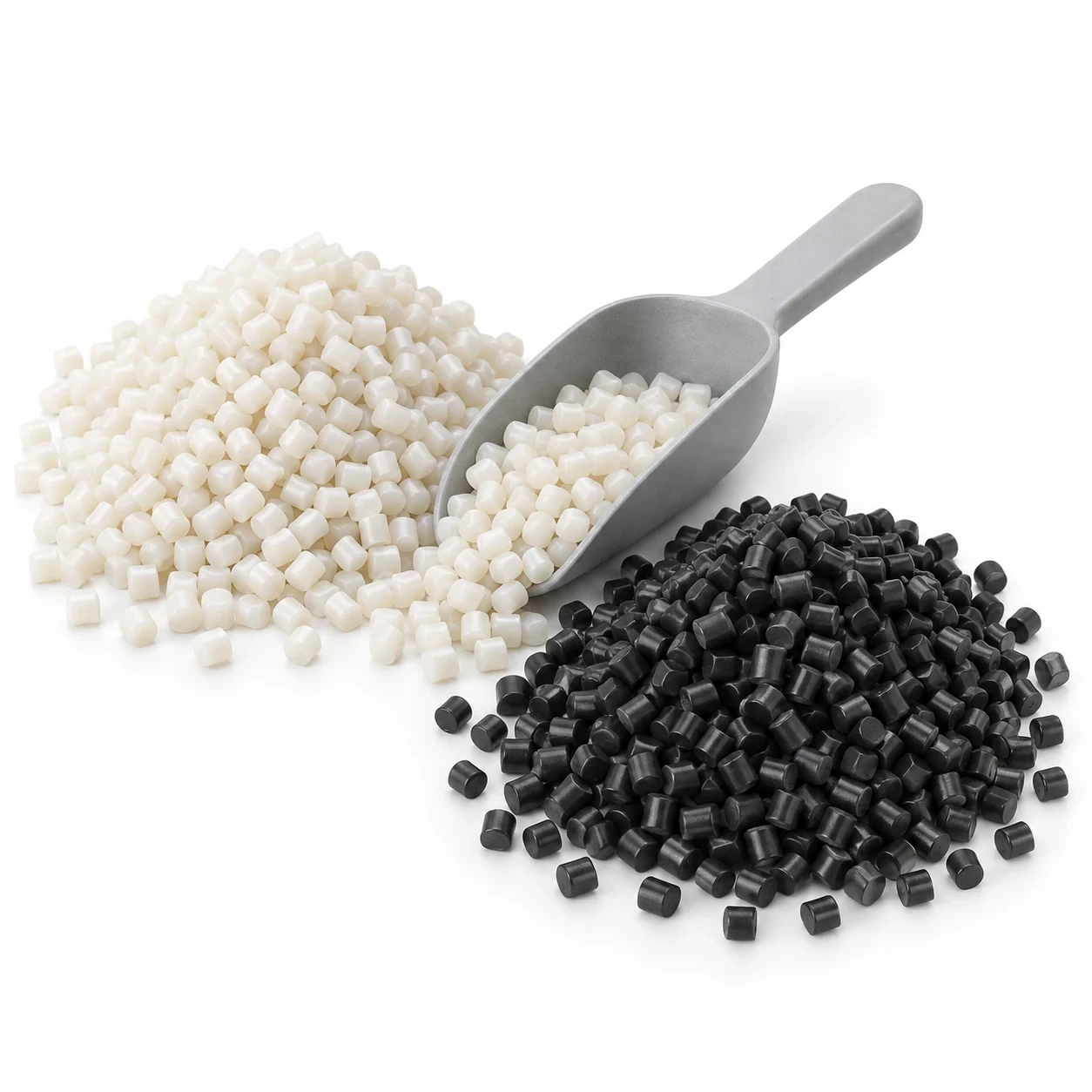
Material names such as PVC, PE, LSZH or nylon are useful starting categories, not complete processing specifications. Maillefer’s low-voltage extrusion guidance distinguishes general-purpose screw applications from dedicated designs for other compounds, and emphasizes stable output over the operating range.2 Do not turn that into a universal rule that every change of material needs a new machine—or that one screw suits every grade.
The practical question is whether the proposed screw, feed system and temperature-control arrangement are suitable for the specified grade at the required output. Ask the supplier to identify which parts of that conclusion come from a comparable test and which still require a trial. If the discussion is actually about compound preparation rather than applying a cable layer, first resolve the single-screw versus twin-screw process boundary.
Decision criterion: Compare candidate machines against both ends of the required operating range. Evidence of sufficient high output does not, by itself, prove stable production of the lowest-demand product. A larger screw is a candidate configuration, not an automatic improvement.
Translate Polymer Demand into a Comparable Output Requirement
For a simple concentric circular layer, start with the polymer cross-sectional area. Let डी be the outside diameter after extrusion and d the diameter immediately before that layer, both in millimetres:
t = (D − d) / 2, where t is the radial wall thickness in mm.
A = π × (D² − d²) / 4, where A is in mm².
Wall thickness alone is not enough: the same radial wall around a larger core uses more polymer per metre. Here, d describes the incoming object under the applied layer, not an assumed empty bore through the finished cable.
If the approved compound density ρ is expressed in g/cm³, the estimated polymer mass per metre is:
m = A × ρ / 1000, where m is in kg/m.
This is a geometry-and-unit conversion, not an extrusion-performance model. One square millimetre of cross-section extending for one metre occupies one cubic centimetre; multiplying by density gives grams per metre. Use the density applicable to the specified compound and the finished solid layer. Do not insert an assumed density simply because two compounds share a family name.
At a required running speed v in m/min, the corresponding continuous polymer demand is:
Q = 60 × m × v, where Q is in kg/h.

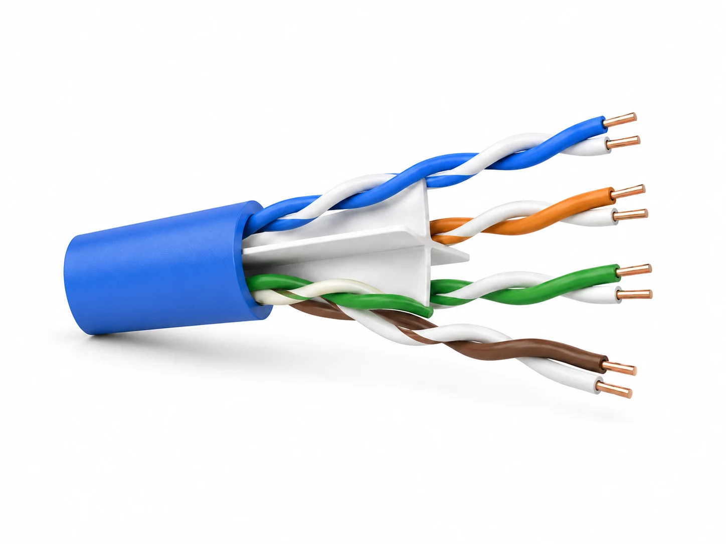
Conceptual illustration—not to scale. For a simple solid circular layer, geometry and compound density estimate polymer demand; the incoming core’s mass is excluded. This calculation is not a line-speed guarantee.
Conversely, if a suitable, sustained output Q has been demonstrated for the material and processing arrangement, the mass-balance speed is v = Q / (60 × m). At unchanged kilograms per hour, doubling the polymer mass per metre halves this theoretical speed. It does not prove that either product can run at that speed on the complete line.
Read the PVC Reference Output Before Applying an Allowance
The HONGKAI reference table supplied for this sizing review lists the following maximum output figures. HONGKAI confirmed that these figures are for PVC. The table does not identify the exact compound grade, density or output-test arrangement, so treat the numbers as reference inputs for preliminary selection—not as a measured guarantee for the customer’s cable.1
| HONGKAI reference model | Listed maximum PVC output (kg/h) | Preliminary output basis at 70–80% of that maximum (kg/h) |
|---|---|---|
| HK-25 | 12 | 8.4–9.6 |
| HK-30 | 38 | 26.6–30.4 |
| HK-40 | 50 | 35–40 |
| HK-50 | 70 | 49–56 |
| HK-60 | 80 | 56–64 |
For an initial comparison that starts from a listed maximum, HONGKAI uses approximately 70–80% of that value as a preliminary planning basis. In symbols, Qplan = α × Qmax, with α = 0.70–0.80 for this company-specific estimating approach.1 The remaining difference is planning headroom; it is not a universal industry rule, an efficiency rating, an accepted-product yield or a contractual running-speed commitment.
Do not apply this factor again to a value that already contains an agreed allowance or is already a demonstrated, project-specific sustained output. Record which basis the quotation uses. The PVC figures do not establish PE, LSZH or nylon output. Those material-specific values remain to be confirmed per project.
Worked Example: Why a 70 kg/h Listing Does Not Prove 50 m/min
The following is a hypothetical, concentric, solid-layer calculation—not a customer product, a PVC grade specification or a machine test. Only the HK-50 listed maximum comes from the supplied reference table; the dimensions, density and target speed are assumed to show the method.
| Example input or calculation | कीमत | स्थिति |
|---|---|---|
| Diameter immediately under the applied layer, d | 4.00 mm | Assumed example input |
| Outside diameter after extrusion, D | 6.00 mm | Assumed example input |
| Radial wall, (D − d) / 2 | 1.00 mm | Calculated |
| Compound density, ρ | 1.40 g/cm³ | Assumed; replace with the specified grade’s value |
| Layer area, π × (D² − d²) / 4 | 15.708 mm² | Calculated |
| Polymer mass per metre, A × ρ / 1000 | Approximately 0.02199 kg/m | Calculated; incoming-core mass excluded |
| Required running speed | 50 m/min | Hypothetical purchasing target |
At that target, the layer requires Qrequired = 60 × 0.021991 × 50 ≈ 66.0 kg/h. Dividing the unadjusted 70 kg/h reference maximum by the same mass per metre gives approximately 53.1 m/min. Looking only at that maximum could therefore make the candidate appear sufficient.
Using HONGKAI’s preliminary 70–80% basis changes the comparison: Qplan = 49–56 kg/h, which converts to approximately 37.1–42.4 m/min for this example layer. The example’s 50 m/min target is above that planning range. Do not close the selection on the 70 kg/h listing alone; review a different configuration or obtain a clearly defined, product-specific output demonstration.
Neither 53.1 m/min nor 37.1–42.4 m/min is a promised HK-50 cable speed. These are mass-balance results under stated inputs. Cooling, tooling, dimensional control, haul-off and take-up still need to support the same product. Confirm the actual compound density and geometry before using the calculation in a quotation.
The circular-layer assumption matters. A sheath over an irregular core, material entering interstices, a foamed layer or a profile with ribs cannot be represented reliably by an unqualified solid annulus. Use the approved cross-section or a representative measured material consumption instead. Record how the mass-per-metre value was obtained so that a drawing change does not silently invalidate the comparison.
Keep separate material streams separate. A main layer, colour stripe and additional outer layer may be supplied by different extruders. A combined polymer total can conceal a shortfall at one extruder; it does not establish the required output for each unit. For a multi-layer product, assign every stream to its own material, geometry and feed arrangement before discussing machine size.
Three output figures should remain distinct: polymer throughput in kg/h, continuous cable running speed in m/min, and accepted cable length over a defined production period. Startup scrap and changeovers affect the third figure. Account for them separately from the preliminary output headroom used to screen a machine size.
If shift output matters, record accepted metres, elapsed production time, startup and shutdown periods, reel changes and rejected lengths using an agreed counting method. Do not quote a universal utilization percentage. A short trial on one continuous run cannot establish a factory’s output across a different order mix.
Note: Use the mass balance to compare requirements and identify missing data. It does not validate melt quality, wall distribution, cooling, tension control or finished-cable performance, and it must not be presented as a guaranteed line speed.
Find the Limiting Stage Before Increasing the Extruder Size
Once the material demand is clear, follow the product through the proposed line. Maillefer’s low-voltage cable insulation reference lists pay-offs, extrusion units, a crosshead, cooling, caterpillars and take-ups as parts of a complete production arrangement.3 For a buyer, the implication is to request a compatible production system rather than compare the main extruder in isolation.
Use observed evidence to identify a limit. If the required material delivery cannot be sustained under the agreed processing conditions, the extrusion stage needs further evaluation. If that delivery is available but the cable fails a dimensional or handling requirement at higher speed, buying more extrusion capacity may not address the cause. These are diagnostic branches, not conclusions that can be drawn from a machine nameplate.

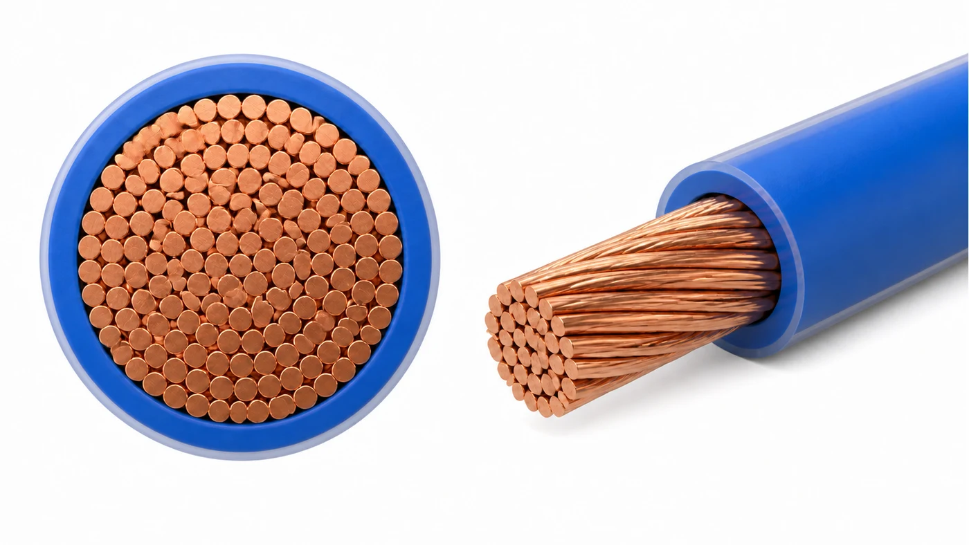
Conceptual review map—not a machine layout or a supplied configuration. Compare the stages using the same product and acceptance target; the illustration does not identify a proven bottleneck or guarantee a higher speed.
| Candidate limit | Evidence to compare during a product trial | Purchasing decision it informs |
|---|---|---|
| Material preparation and extrusion | Agreed material condition, stable delivery and relevant process records | Whether the compound and proposed extruder arrangement have been demonstrated together |
| Crosshead and tooling | Actual input construction, tooling identification, wall and eccentricity results | Whether a tooling or flow-distribution review is needed before changing main-machine size |
| Cooling | Product condition after cooling, available cooling arrangement and recorded water conditions | Whether cooling capacity or configuration needs review at the target speed |
| Haul-off and tension control | Running condition, slippage or deformation observations and dimensional results | Whether the transport arrangement supports the product without introducing defects |
| Take-up and reel handling | Reel dimensions, package formation, tension behaviour and change sequence | Whether the required package and operating sequence are supported |
Cooling deserves its own review because the available floor length is not a complete cooling specification. Maillefer’s cable cooling system description explicitly relates the arrangement to process needs, cooling capacity and floor space, with different module and temperature-zone options.4 That supports a configuration review—not a claim that a particular trough length will suit every material, wall thickness and speed.
Likewise, outside diameter alone cannot close the tooling decision. A product can meet its overall diameter target while still requiring a separate wall-thickness or eccentricity check. Use the crosshead and tooling guide for that detailed review rather than treating every dimensional problem as insufficient extruder output.
For an existing line, describe what is already installed before asking for an upgrade. Relevant evidence includes machine identification, the actual screw and crosshead arrangement where known, cooling layout, haul-off type, reel interfaces and available control documentation. Unknown information should be marked unknown; a photograph of the extruder alone does not establish that a new downstream unit can be connected safely and controlled correctly.
An upgrade proposal should therefore name its boundary: main-machine change, material preparation, tooling, cooling, handling, controls, or a combination. Ask which existing equipment is retained and what evidence supports that reuse. A supplier should not have to infer the whole line from the desired finished diameter.
The same approach applies to a new केबल शीथिंग लाइन: use the product page to understand the equipment scope, then resolve the specific material and product envelope in the configuration. Published equipment examples are references, not a substitute for a project-specific output commitment.
Accept a Tested Product Range, Not an Unqualified Maximum
The final selection should connect the product-envelope table to the trial record. If the factory needs several products, identify what each selected trial product is intended to prove. One may address high polymer demand; another may address the low-demand operating condition or a different compound. A successful trial should not be stretched to cover untested materials, constructions or reel arrangements without an explicit engineering basis.
HONGKAI’s previously confirmed acceptance approach separates an extruder output check from a complete-line cable run. Under agreed conditions, an output check can measure material delivery by weight over time. A line trial then uses the specified cable and evaluates running speed together with the agreed product requirements. Keep these records separate: neither result replaces the other.
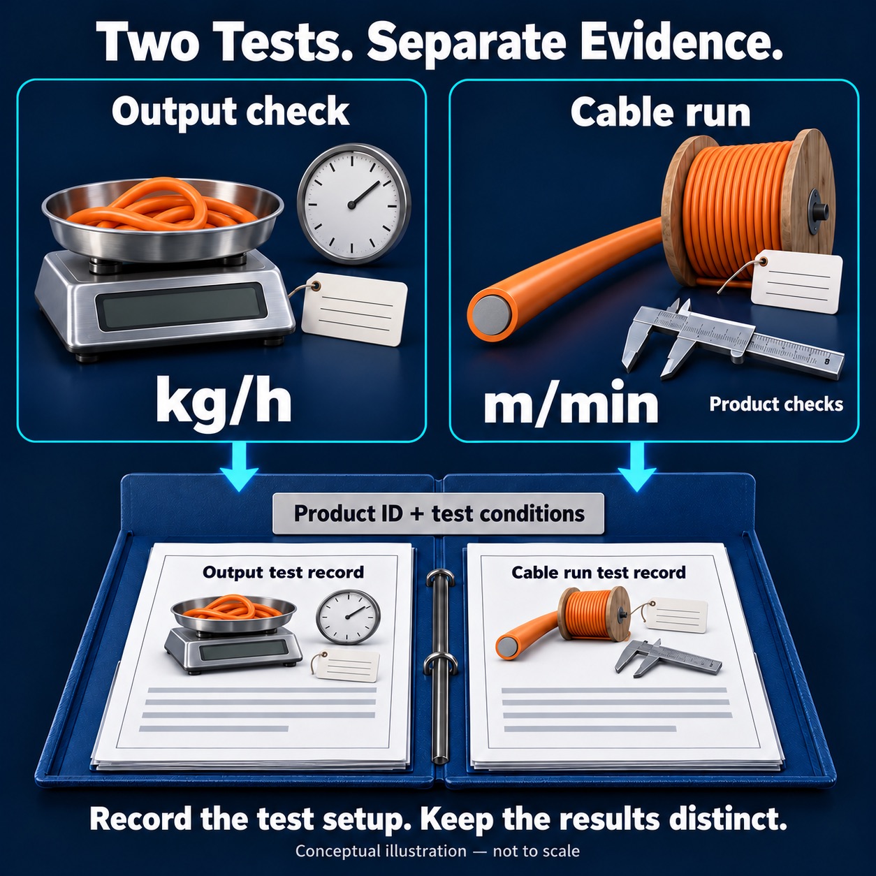
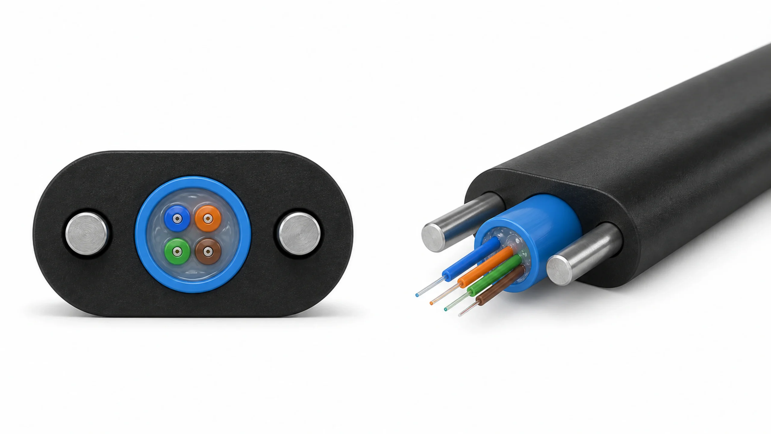
Conceptual illustration—not a completed test or report. Weighed material output and cable-run evidence need separate records linked to the identified product and test conditions; the blank pages contain no measured results or acceptance decision.
Before ordering, agree what the output test actually contains. An open-head material-delivery result must not be relabelled as delivery through the production crosshead and tooling. Record the test configuration, material, time interval and measurement method. When a report omits those conditions, its kg/h figure is not a like-for-like basis for comparing quotations.
For the line trial, connect each sample and production record to the product drawing, compound grade, tooling and reel arrangement used. Retain the agreed dimensional results and any other product tests assigned to that trial. A machinery run does not automatically establish all electrical, mechanical, fire or regulatory properties required of the finished cable; those tests and responsibilities need their own agreed scope.
Evidence to request: A configuration revision, identified trial products, recorded material and tooling, the measured output and cable-run results, the agreed acceptance criteria, and a clear statement of what was not tested. Use the same product identifiers in the quotation, contract and acceptance record.
If a candidate fails one part of the envelope, make that limitation visible. The purchasing response might be a different configuration, a restricted initial product range, a separate production route or a further trial. It should not be an unsupported promise that adjustment during commissioning will resolve every difference.
The machine-size decision is complete when each required product has a traceable status: demonstrated under the agreed conditions, pending a defined test, or outside the supplied scope. That is more useful than choosing the largest extruder and discovering the boundaries after installation.
-
HONGKAI, PVC extruder technical-parameter reference table and topic-specific sizing explanation supplied for this article on 3 November 2026. The reference lists HK-25/30/40/50/60 outputs of 12/38/50/70/80 kg/h. The 70–80% basis is HONGKAI’s preliminary estimating approach, not a test certificate or product-speed guarantee; compound grade and test conditions remain project-specific. ↩ ↩ ↩
-
Maillefer, LV Cable Extrusion Value, discusses stable output over the operating range and material-related screw choices. This is independent technical context, not a HONGKAI performance specification. ↩
-
Maillefer, Low Voltage Cable Insulation, lists extrusion, crosshead, cooling and cable-handling components within its complete-line configurations. Its machine ratings and production speeds are not transferred to HONGKAI equipment. ↩
-
Maillefer, Cooling System MCS 20 C, describes cable cooling arrangements selected for process needs, cooling capacity and space. Its model-specific limits are not transferred to HONGKAI equipment. ↩

 English
 हिन्दी
 فارسی