
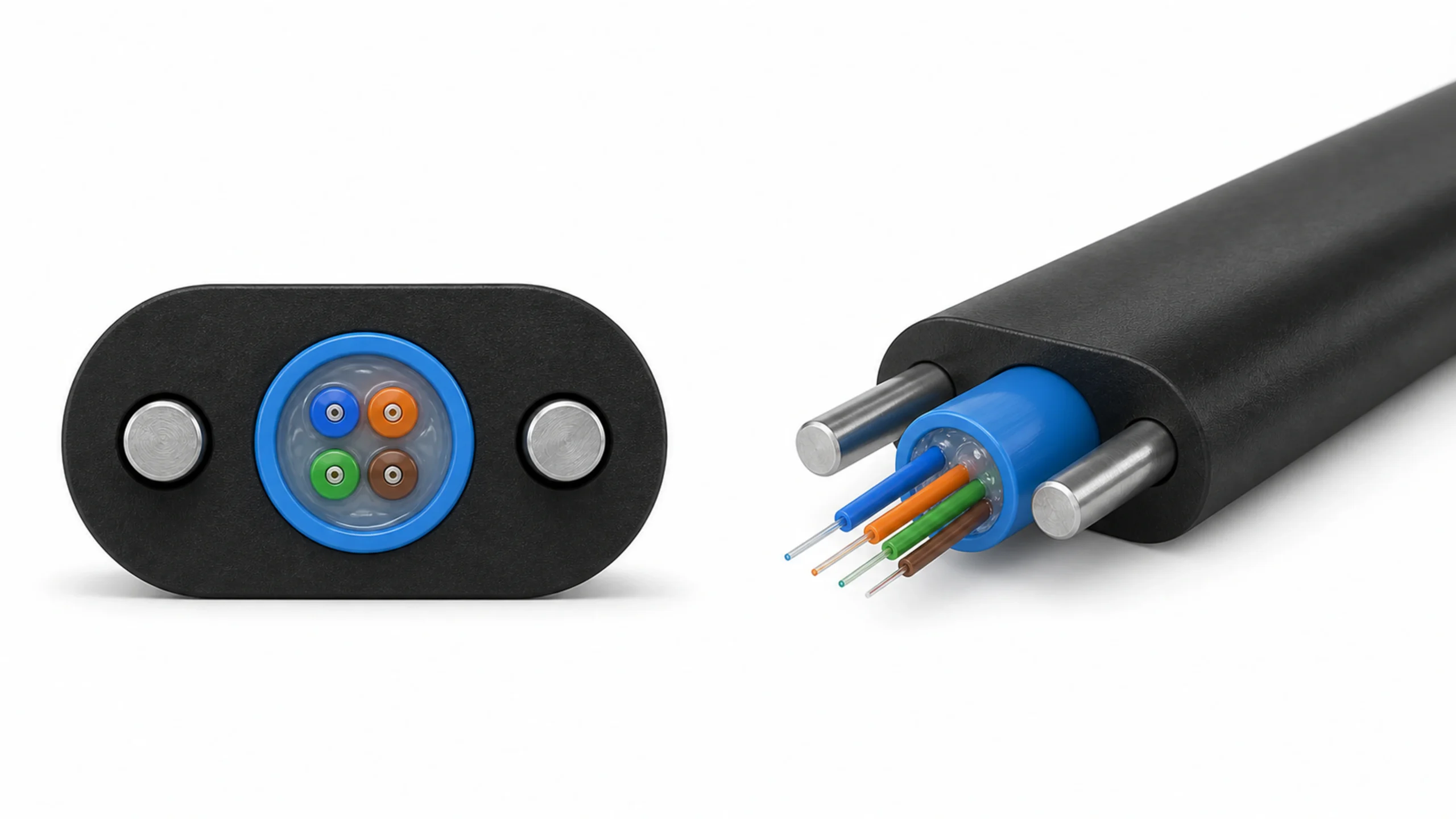
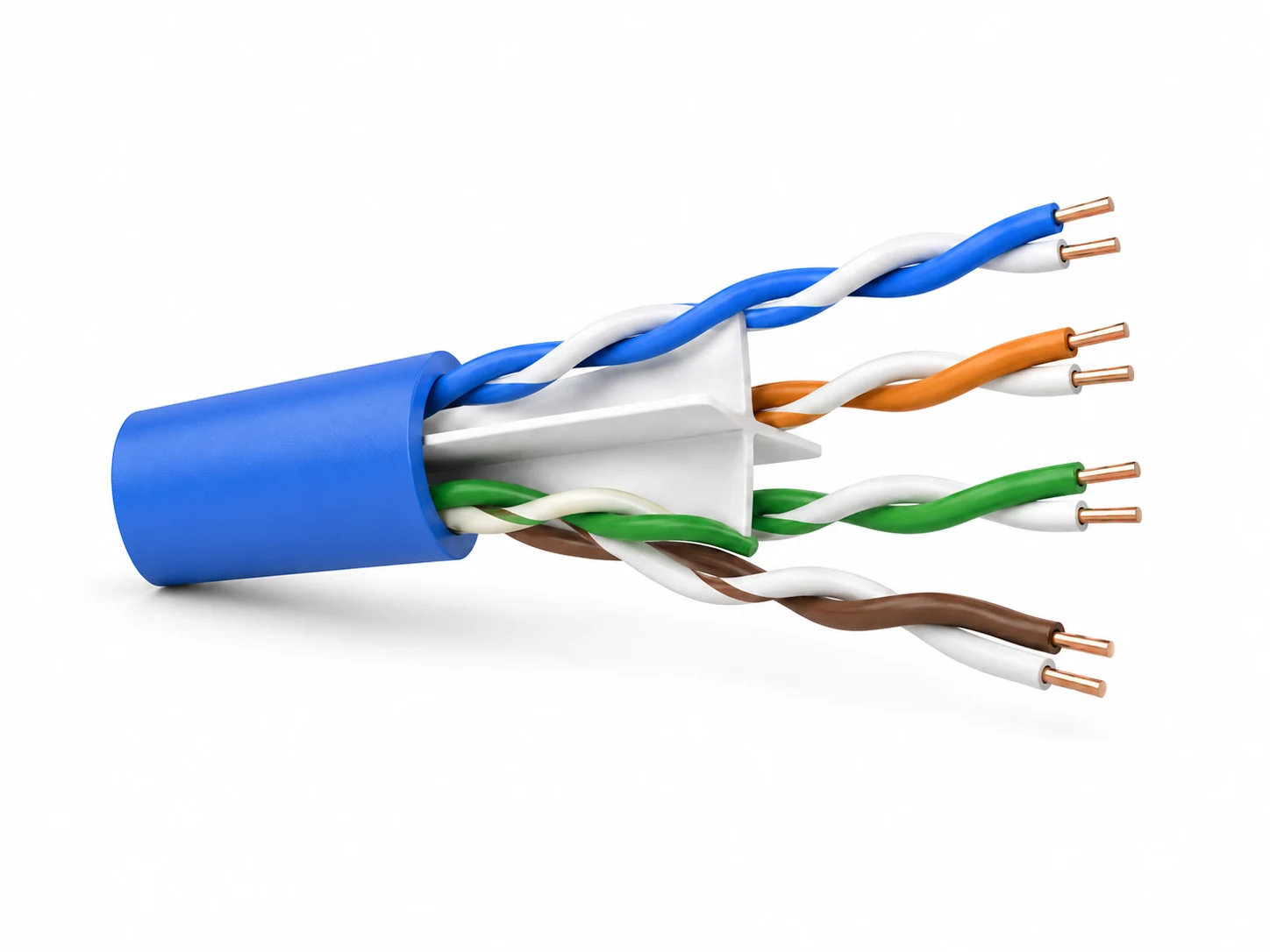
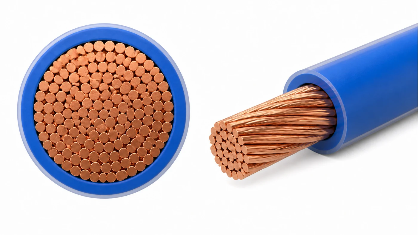
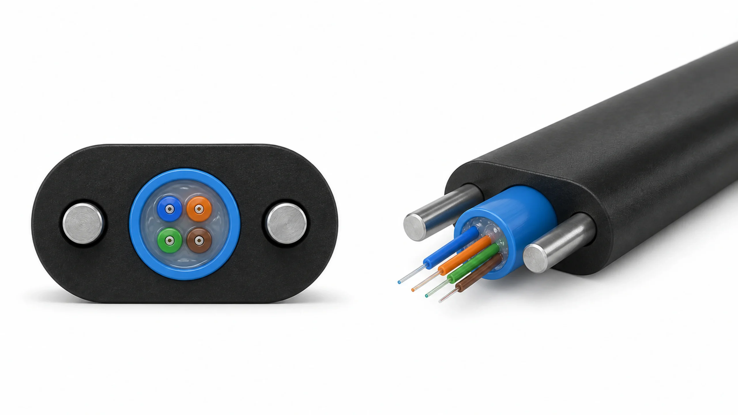

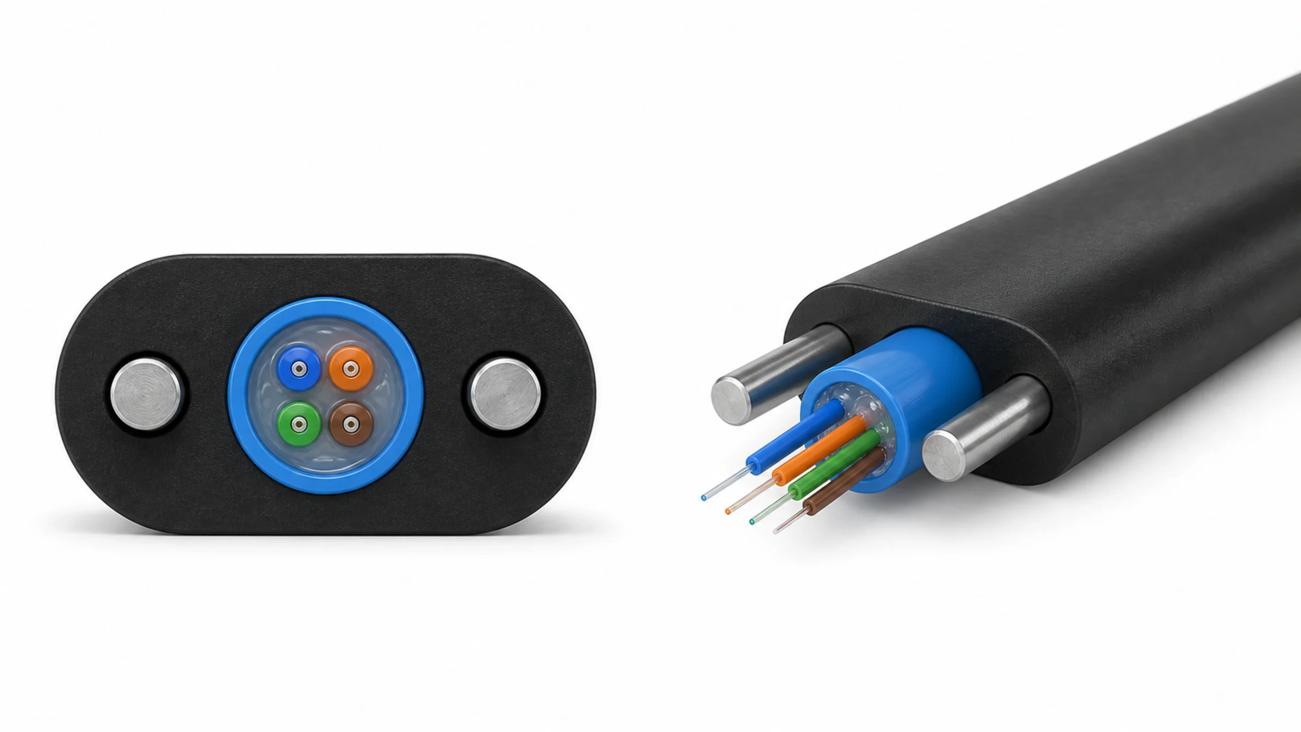

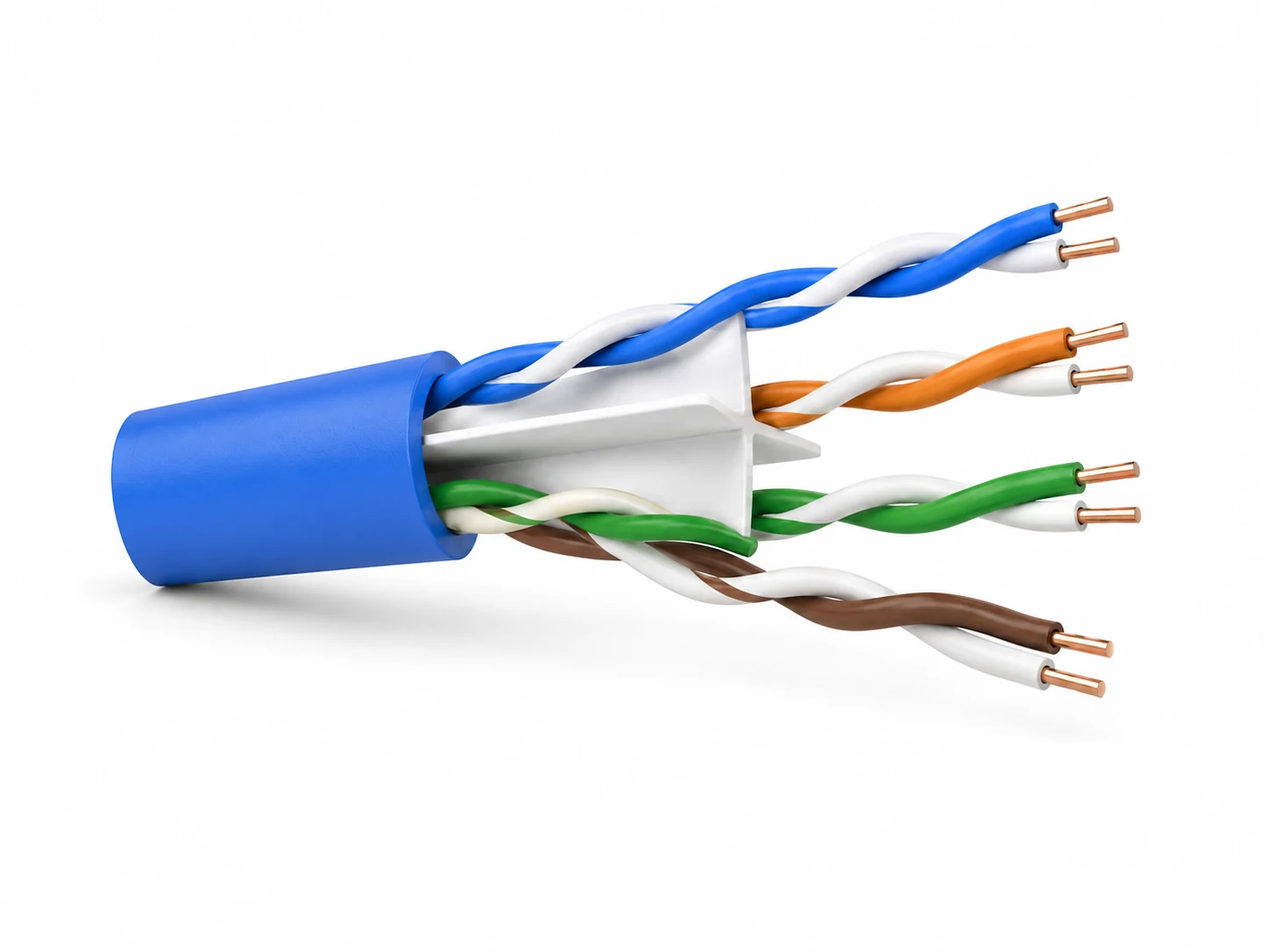










A LAN cable factory adding shielded products needs to decide which manufacturing stages actually change, not simply whether a quotation contains a foil machine. Factory owners, production managers and technical buyers should compare the approved cable construction with the equipment, production flow and evidence already available.
Shielded LAN cable is not one production route. Overall foil, individually screened pairs and an overall braid require different material-handling functions. Define those layers first, then check whether the existing insulation, pair twisting, cabling, sheathing and testing arrangements can support the new product.
The useful comparison is therefore a construction-to-process map. It separates the work that creates the screen from the upstream controls that still determine the cable geometry, and from the tests needed to accept the finished product.
Read the Screening Code Before Comparing Machines
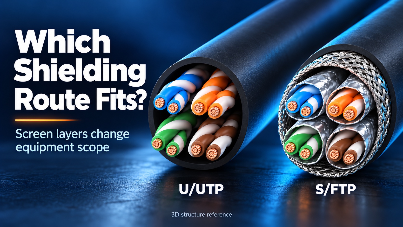
The letters on either side of the slash answer different questions: what screens the complete cable core, and what screens the individual twisted pairs. A purchase enquiry that says only FTP or STP can leave that distinction unresolved. Fluke Networks explains several of these designations; Belden’s construction table also distinguishes U/FTP from F/UTP.12
| Defined construction | Overall metallic screen | Individual-pair screen | Manufacturing scope to identify |
|---|---|---|---|
| U/UTP | None | None | Pair formation, cable assembly and jacket; any nonmetallic tapes remain design-specific |
| F/UTP | Foil | None | Overall foil application and the drain-wire arrangement, if specified |
| U/FTP | None | Foil | Individual-pair foil application before the screened pairs form the cable core |
| S/FTP | Braid | Foil | Individual-pair foil application plus overall metal braiding |
| SF/UTP | Foil and braid | None | Overall foil and braid, without assuming individual-pair screens |
Treat this table as a layer map, not a ranking of product quality. The screening code does not define the conductor construction, insulation compound, jacket, finished diameter, transmission category or acceptance program. Those inputs still belong on the cable drawing and product specification.
Keep the drawing and code consistent. If a document says S/FTP but its section shows only one overall foil, stop the equipment comparison and resolve the intended construction. Do not let a machine list silently decide which product the customer will receive.
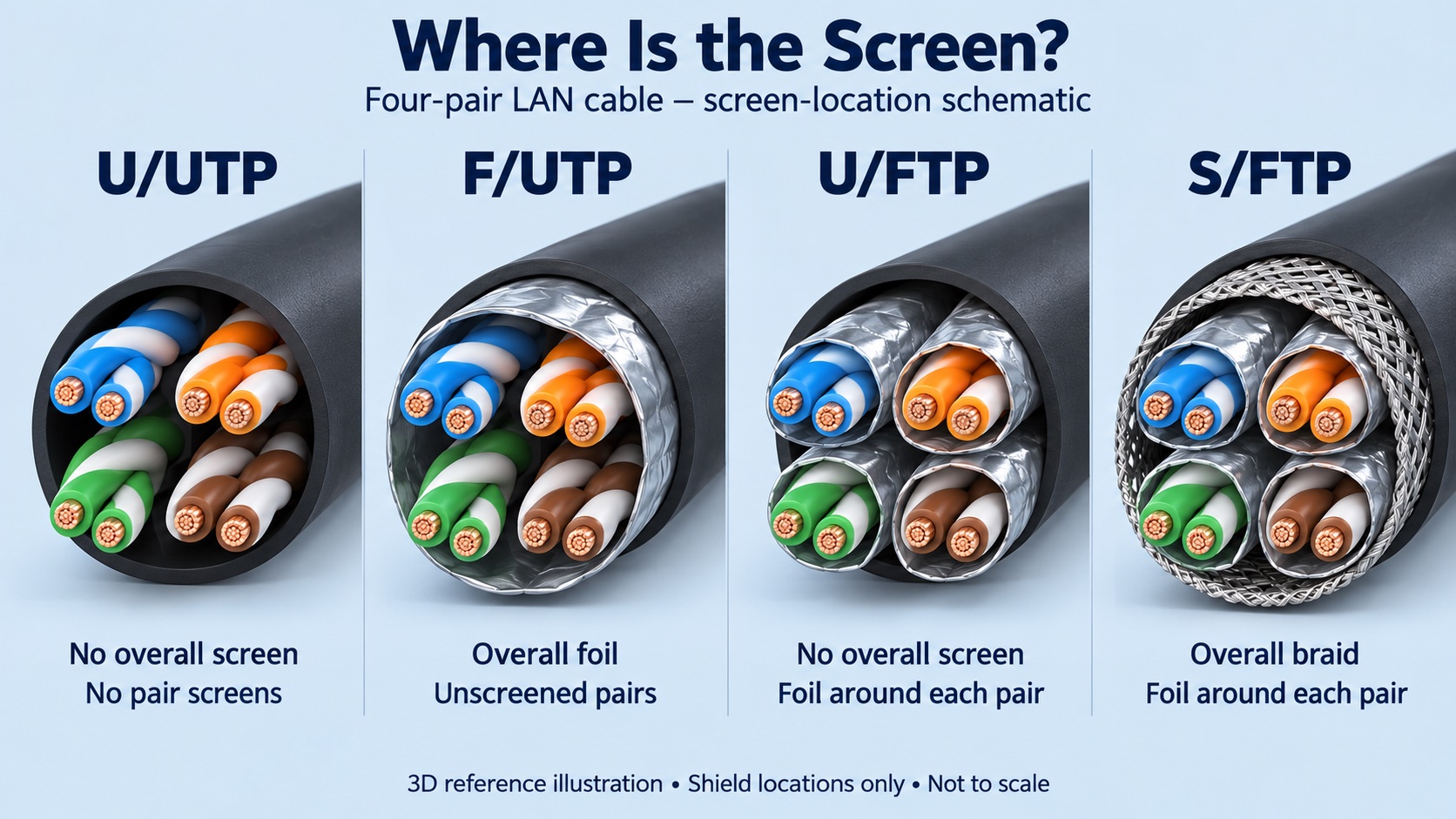
3D reference illustration of four-pair screen locations. Conductor build and other construction details are simplified; the drawing does not establish a cable category, specification or delivered HONGKAI configuration.
Decision criterion: Before accepting a shielding-equipment price, identify the screen around each pair, the screen around the assembled core, and every separately specified drain wire or supporting tape. Attach those identities to the drawing revision used for quotation.
Translate Each Screen Into an Equipment Function
An overall wrapper cannot be counted as proof of individual-pair screening, and foil application cannot be counted as metal braiding. Compare the required functions and their position in the process before comparing machine names or quantities.
Begin with the material entering the factory. Solid conductor and stranded conductor are different inputs; a conductor-bunching stage is not added merely because the finished cable is shielded. The insulation and pair-forming routes must match that input and the approved cable design.
The next decision is where screening happens. An overall foil surrounds the assembled pair core. Individual-pair screening requires the specified foil to be applied to each relevant pair before those screened pairs are assembled. An overall braid is another physical layer with its own equipment and input materials. Whether taping is integrated with a cabling unit or arranged as a separate operation must be shown in the offered layout rather than inferred from the construction name.
Foil screening and core assembly can belong to the same integrated cabling arrangement without becoming the same physical operation. The proposed layout must show where each pair receives its screen and where an overall screen surrounds the core. Sharing a machine frame does not turn one overall foil wrapper into individual-pair screening equipment.
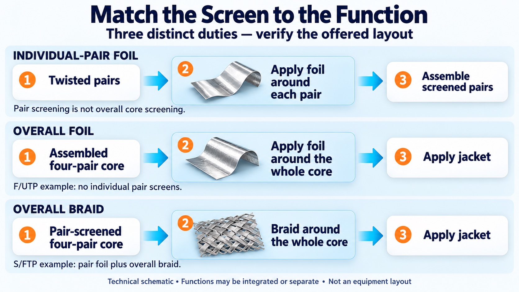
Technical function map separating individual-pair foil, overall foil and overall braid. The rows are construction-specific examples, not one universal machine arrangement; integrated and separate operations must be verified in the offered layout.
| Function to place on the route | Buyer input to supply | What the equipment proposal should explain |
|---|---|---|
| Individual-pair foil application | Pair dimensions, tape specification and approved wrapping arrangement | Pair feed, tape feed, tension adjustment, guiding, monitoring and connection to the next stage |
| Overall foil application | Assembled-core dimensions, tape and drain-wire details where required | Foil path, applied-layer arrangement, drain-wire feed and control of the core through the wrapping zone |
| Overall metal braiding | Core entering the braider, braid material and construction requirements | Braiding function, material preparation, take-up package and interface with sheathing |
| अंतिम शीथिंग | Screened-core envelope and jacket specification | Pay-off, tooling, guide path, jacket application, cooling and take-up suitability |
HONGKAI’s current LAN cable production guide treats foil, drain wire and braid as construction-dependent scope rather than equipment required on every LAN line. Existing HONGKAI reference configurations also list powered pair-taping heads, overall wrapping and cantilever cabling functions. A separate reference chapter covers metal braiding. These are documented equipment families, not evidence that one historical package is suitable for every screened cable.
For the foil-screening duty discussed in HONGKAI’s current equipment review, active tape pay-off is the starting arrangement for managing tension. During the trial, inspect tension consistency and the applied overlap, including excessive overlap, against the approved wrapping requirement. Establish the actual tape path, material and settings first; do not apply one tension or overlap value to every foil or cable. A historical wrapper’s powered or passive options for other duties do not establish the correct mode for this product.
For a live quotation, ask the supplier to mark each function as included, integrated into another machine, separately supplied or outside scope. Include the supporting reel and material-preparation arrangements. A row labeled shielding is not a complete answer if nobody can show which layer it produces.
Check Reuse and Capacity Without Assuming One Common Speed
Start a UTP retrofit with an inventory of the equipment actually installed and the shielded construction the customer intends to make. For a move from U/UTP to overall-foil F/UTP, an added foil pay-off and application function around the cabling operation may be the main change to investigate. It is not an automatic drop-in conversion, nor does it establish a route for individually screened pairs or metal braiding. Review the actual incoming and outgoing packages, material paths, control interfaces and product envelope at each connection, then distinguish what can be reused unchanged from what needs modification or replacement.
For an existing U/UTP factory, a useful review begins with four physical questions:
- Which pair-forming, cabling, pay-off, sheathing and testing machines are installed, and what drawings, models and operating records identify their actual scope?
- Do the incoming pair/core dimensions and available reels fit the proposed screening stage? Confirm reel dimensions, mounting and handling requirements rather than matching the nominal cable diameter alone.
- Can the cabling path, tape feed and existing speed/tension controls support the proposed arrangement? Show the required connections and verify coordinated running and stopping; do not assume compatibility from the presence of a PLC.
- Can the screened-core envelope pass through the sheathing guides and tooling, and can the test system assess the resulting product using the agreed sample preparation and limits?
These questions do not establish compatibility by themselves. They identify the drawings, operating records and supplier checks required before the quotation can call an item reusable.
For a UTP-first project with later shielding planned, work backwards from the intended future cable drawing. Identify which screening duties would be added at pair preparation, core assembly or braiding, then check their material paths, reel access, footprint and control connections against the initial layout. Reserve only the interfaces and space that the reviewed arrangement actually needs. This is not a reason to buy every shielding machine immediately or a promise that any future product can be added without changes.
Keep capacity on the same basis. A tape-head rotational rating, pair-processing speed, cabling speed and finished-cable output are not interchangeable figures. Ask each supplier for the same target product, defined quality conditions and saleable-output basis. Where a stage is offline, include its intermediate reels and handling rather than treating the full factory as one continuously linked machine.
| Capacity entry | Quote basis to identify | Evidence needed on the common output basis |
|---|---|---|
| Insulation and pair supply | Insulated-wire or qualified-pair length per stated period | Required quantities for the approved pair count and finished-cable target |
| Pair-screening stage | Output per pair, per head or complete pair set; simultaneous or sequential operation | Qualified output for each pair type, actual head allocation and the pair-consumption basis |
| Core assembly and overall screening | Qualified assembled-core length per stated period | The approved construction and input/output length relationship for that configuration |
| Braiding, where specified | Qualified screened-core length per stated period | The required braid construction and the material-preparation work included |
| Sheathing and final release | Accepted finished-cable length per stated period | Identified product and acceptance result, not the highest upstream speed display |
| Shared operating period | Clock hours or head-hours, with running time and excluded time identified | Available time, changeovers, reel handling and rejects counted on one consistent basis |
For a braiding proposal, obtain the outside diameter of the incoming core, the intended braid-wire count and arrangement, the required braid construction, and the material and finished-core reel sizes. Inspect an identified trial sample for gaps, uneven results or other departures from the approved design. These product and package inputs must be established before a rate is offered. Include the agreed wire preparation and reel-change work in the time basis rather than treating the displayed braider speed as finished-cable capacity.
A simple planning calculation is useful when its inputs are measured or supplied for the actual product:
Accepted output for a stage = qualified output rate × available production time.
Convert pair-stage output to the required finished-cable basis before comparing stages. Where that conversion depends on the actual lay and material-consumption relationship, request the project’s conversion basis; do not substitute a nominal reel length. The proposed factory output cannot exceed the smallest supported stage capacity on that common basis, but that comparison alone does not establish a workable production schedule.
Check the load on any shared screening resource. If one head processes different pair types one after another, the required runs compete for the same available hours. Do not assign a full shift of that head’s capacity independently to every pair type. For this sequential case, calculate each run on the same qualified-length basis:
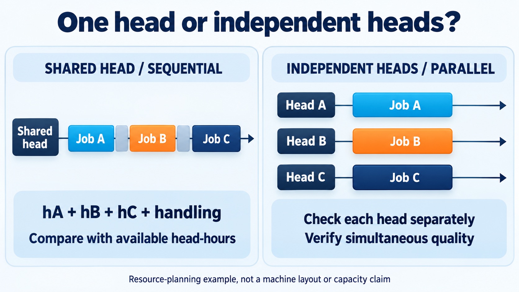
Illustrative workload model: a shared head must cover its sequential run and handling hours. Genuinely parallel heads need separate load checks and evidence of simultaneous quality. Blocks are not to scale; the three example jobs are not a cable-pair count, purchased-head quantity or offered machine configuration.
Run hours for one pair type = required qualified screened-pair length ÷ qualified screened-pair output per running hour.
Add those run hours for every pair type assigned to the shared head, then add the agreed non-running changeover and reel-handling hours. Compare that total with the hours actually available to that head in the chosen period. The required pair length must reflect the approved pair count and verified consumption per finished metre; it is not automatically equal to the planned finished-cable length.
Where heads genuinely operate in parallel, check each head’s assigned load separately and verify that the offered combination can maintain the required quality simultaneously. Do not multiply a per-head rating by the number of heads without that operating basis. This is conditional scheduling arithmetic, not a claim about the layout or output of a particular HONGKAI package.
Use losses only once. A rate measured as qualified output over an entire shift already includes the stops and rejected output inside that measurement. Do not deduct those same losses again as if the figure were a running-only rate. The quotation should identify the clock interval, accepted-length basis, shared resources and exclusions before it states a factory-output commitment.
Note: This comparison sets no universal shielding speed, equipment count, scrap allowance or payback period. A historical maximum rating is not a guaranteed production rate for a different cable, foil, braid or acceptance requirement.
Accept the Cable Construction and the Evidence Together
The trial should demonstrate both the required screen construction and the finished cable result. A neat foil layer is not a substitute for electrical evidence, while an electrical result without an identified sample cannot explain what equipment and materials produced it.
In the production review described for this article, the basic finished-product checks include outside diameter and agreed transmission measurements after the jacket is applied. Where a Fluke instrument is proposed, record its model, the sample and connection arrangement, selected test limits and complete result file. The brand name alone does not define the test.3 Specify any additional measurements or laboratory work from the customer’s actual acceptance requirements; do not represent a convenient PASS as evidence for every screen property or bulk-cable qualification requirement.
Use a construction-specific trial sheet rather than one generic shielded-cable checkbox. The proposed checks below require agreement before the trial; they are not a universal product standard or a claim that HONGKAI has already supplied each test function.
| Trial record | What to connect to the identified sample |
|---|---|
| Approved input | Cable drawing revision, conductor and insulation inputs, tape/braid material and reel identities |
| Applied screens | The actual pair and overall layers, the specified wrapping or braid condition, and drain-wire arrangement where required |
| Operating setup | Offered equipment configuration, settings, trial conditions, observed alarms and handling steps |
| Finished construction | Core and cable dimensions, surface condition and agreed examination method |
| Electrical evidence | Acceptance object, governing requirements, sample preparation, fixture, instrument/calibration status and complete results |
| Unresolved scope | Untested products, unobserved conditions, excluded equipment and required corrective work |
Agree the numerical criteria with the responsible product and equipment specialists. Do not copy a foil-overlap percentage, braid-coverage target or tension value from an unrelated product and call it the acceptance limit. A visual inspection and a continuity check answer narrower questions than a complete performance evaluation.
Fluke Networks describes a further boundary in installed shielded links: a simple DC continuity result can be misleading when the signal has an alternative grounding path.4 That field-testing example explains why the test arrangement matters. It is not a factory bulk-cable test method, an electrical-installation instruction or proof of shielding effectiveness for every manufactured reel.
The Cat6 factory and field-test guide separates bulk-cable qualification, production-lot release, component assessment and installed-link testing. Use the correct acceptance object for the order. If the factory sells bulk cable rather than connectorized assemblies, do not quietly replace its agreed laboratory requirements with a convenient installed-channel PASS.
Evidence to request: Keep the approved construction, supplied configuration, operating record, identified samples and applicable test results together. Show which trial supports each offered product and mark every untested extension explicitly.
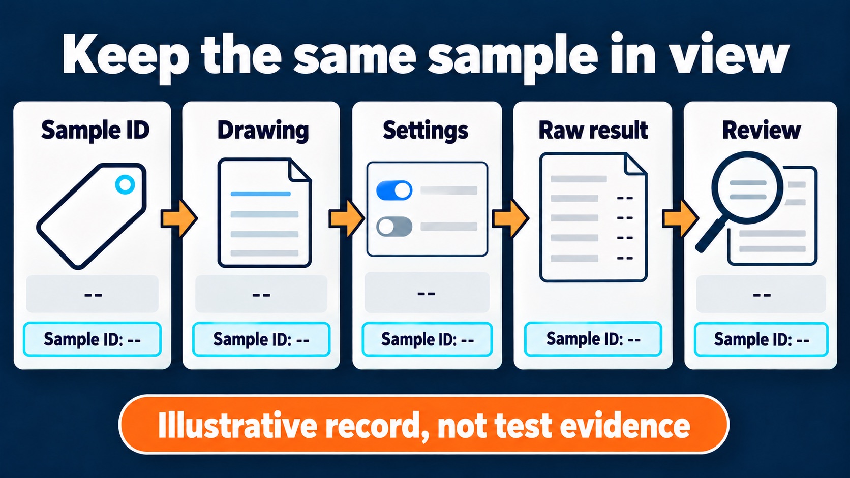
Illustrative record linkage, not test evidence. Keep one sample identifier connected to the approved drawing, recorded settings, complete raw results and review; all fields in this example are intentionally blank.
The comparison is ready for a purchasing decision when each required screen has an assigned process, each reused stage has a supported compatibility decision, each capacity figure uses a comparable basis, and each promised product has an agreed evidence plan. Until those connections are visible, a longer machine list is not a more complete production solution.
-
Fluke Networks, Acronyms for balanced cables, checked 18 October 2026. Used for screening-designation terminology, not as a current product-compliance certificate or a machinery specification. ↩
-
Belden, Shielded Cabling Systems — product bulletin NP132E, page 2, construction table; checked 18 October 2026. Used only for the location/type of screens, including U/FTP. The historical bulletin’s performance promises, warranty and numerical product specifications are not adopted here. ↩
-
Fluke Networks, Choosing the Test Limit — DSX CableAnalyzer, 25 November 2020, checked 23 October 2026. Used only to explain that adapters, test limits and the test scenario must match. No DSX model, factory fixture or bulk-cable qualification method is attributed to HONGKAI. ↩
-
Fluke Networks, How to Test Shield Integrity?, 15 February 2017, checked 18 October 2026. Used only for the alternative-ground-path limitation in installed-link continuity testing. Factory cable qualification requires its own agreed method and evidence. ↩

 English
 हिन्दी
 فارسی