



LAN Cable Production Lines & Equipment
Start with the LAN cable category and electrical performance you need to achieve. HONGKAI connects conductor preparation, insulation, pair twisting, cabling, shielding, sheathing and testing into one practical production route.
- Core production stagesconfigured around the target cable
- Electrical performancetranslated into process control
- Layout and utilitiesconsidered with the line
- Installation and supportconnected to project startup
What Type of LAN Cable Are You Planning to Produce?
Select the target category first. The page will translate that decision into performance priorities, process requirements, related equipment and an enquiry brief.
Cat6 F/UTP & Shielded Cable
Shielded enterprise and industrial network environments
- Frequency orientation
- 250 MHz typical
- Conductor orientation
- 23 AWG typical
- Shielding structure
- Foil and drain wire
- Production difficulty
- 04 / 05
- Foil overlap control
- Drain-wire continuity
- Pair balance through shielding

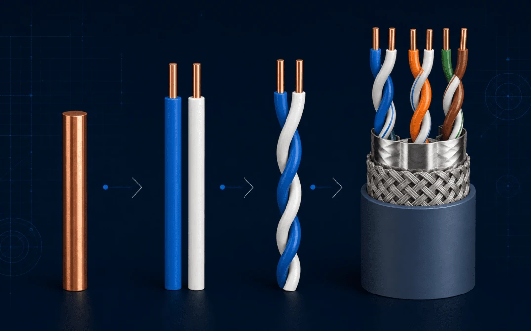
From Copper Conductor to Verified, Packed LAN Cable
All eight stages remain visible. Selecting a stage carries its equipment focus into the next section without hiding the rest of the production route.
- 01Conductor Preparation
- 02Insulation Extrusion
- 03Pair Twisting
- 04Cabling
- 05Shielding
- 06Outer Sheathing
- 07Electrical Testing
- 08Coiling & Packing

Prepare the conductor route required by the approved cable design.
- Input
- Copper rod or incoming conductor
- Critical control
- Diameter tolerance and surface condition
- Output
- Prepared copper conductor
- Equipment
- Drawing, annealing, pay-off and preparation systems
Apply stable insulation with dimensional and process monitoring.
- Input
- Prepared conductor and insulation compound
- Critical control
- Diameter, concentricity and material consistency
- Output
- Insulated core wire
- Equipment
- Insulation extrusion line and inline gauges
Twist two insulated wires with controlled pitch, symmetry and tension.
- Input
- Two insulated wires
- Critical control
- Twist pitch, pair balance and tension
- Output
- Controlled twisted pair
- Equipment
- Pair twisting machine and tension-control route
Lay up four pairs around the confirmed central construction.
- Input
- Twisted pairs and separator if required
- Critical control
- Pair position, lay length and tension
- Output
- Cabled core
- Equipment
- Cabling line and separator application
Apply the confirmed foil, drain-wire or braid structure without disturbing pair geometry.
- Input
- Cabled core and shielding material
- Critical control
- Overlap, coverage, continuity and tension
- Output
- Shielded cable core
- Equipment
- Foil applicator, drain-wire feed and braiding systems
Apply the final jacket while protecting the controlled cable geometry.
- Input
- Cabled or shielded core and jacket compound
- Critical control
- Wall thickness, ovality, cooling and print quality
- Output
- Finished LAN cable
- Equipment
- Outer sheathing extrusion line
Verify the agreed electrical parameters and retain traceable test evidence.
- Input
- Finished cable sample or reel
- Critical control
- Test setup, frequency range and acceptance criteria
- Output
- Project-agreed test record
- Equipment
- Electrical test and measurement systems
Prepare the finished cable for the confirmed pack length and delivery format.
- Input
- Tested finished cable
- Critical control
- Length, tension, coil geometry and labelling
- Output
- Coiled or boxed finished cable
- Equipment
- Coiling, take-up and packing systems
Process note: Required and optional labels follow the selected category. Final process stages, equipment source and acceptance criteria remain subject to the approved cable specification.
Browse Machines the Way the Line Is Built
The established process Accordion remains on the left. Opening a group updates the related real/reference equipment image and control summary on the right.
- Wire drawing machine
- Annealing system
- Copper pay-off and preparation
Incoming copper format, conductor design and responsibility boundary are confirmed per project.
- Insulation extrusion line
- Crosshead, cooling and haul-off
- Inline dimensional monitoring
Final configuration follows conductor size, insulation material and agreed control requirements.
- Pair twisting machine
- Pay-off and tension control
- Back-twist configuration where required
Pair design, lay-length window and target cable determine the selected configuration.
- Cable twisting line
- Separator application where required
- Wrapping and take-up systems
Central construction, pair position and downstream shielding route require joint confirmation.
View cross-web separator line reference- Aluminium-foil application
- Drain-wire feed
- Braiding equipment where required
Shield material, overlap, coverage and equipment source are confirmed in the approved scope.
- Outer sheathing extrusion line
- Cooling, haul-off and take-up
- Inline marking and spark-test interface
Jacket material, finished diameter and pack format define the final line arrangement.
- Cable test and measurement system
- Project-agreed sample preparation
- Traceable test-record workflow
Test standard, frequency range and acceptance criteria require written project confirmation.
- Coiling and take-up systems
- Length-control interface
- Packing system for the agreed format
Pack length, coil geometry, labelling and downstream scope remain project-specific.
Shielding
Apply the confirmed foil, drain-wire or braid structure without disturbing pair geometry.
- Critical control
- Overlap, coverage, continuity and tension
- Related equipment
- Foil applicator, drain-wire feed and braiding systems
Safe reference only — a verified shielding-equipment image is not yet assigned. Foil, drain-wire and braid scope are confirmed in the proposal.
Choose a Route, Then Review the Technical Detail
Browse HONGKAI product-detail pages alongside clearly labelled planning routes. Product pages open the technical detail; planning cards continue the comparison and enquiry workflow.
01 · CAT5/5E Cat5 Cable Production Line
A dedicated Cat5 product route covering conductor insulation, pair twisting, cabling, outer sheathing and supporting checks.
02 · CAT5/5E Cat5e Ethernet Cable Production Line
A Cat5e-focused detail page for buyers comparing the required extrusion, twisting, cabling and sheathing stages.
03 · CAT5/5E UTP Cat5e Production Route
A dedicated UTP Cat5e route from insulated conductors and controlled pairs through cabling, sheathing, testing and packing.
04 · CAT5/5E Ethernet Cable Production Line
Use this broader product page when the exact category is still being confirmed but the buyer needs the complete manufacturing route.
05 · CAT6/6A UTP Cat6 Production Route
A Cat6 UTP route emphasizing precision insulation, pair twisting, cross-separator control, cabling and final electrical verification.
06 · CAT6/6A Cat6 Ethernet Cable Production Line
A dedicated Cat6 detail page for reviewing the connected extrusion, pair-twisting, cabling and sheathing equipment stages.
07 · CAT6/6A Cat6 Plenum Cable Production Line
An application-specific route for buyers who need the cable construction, material plan and connected production stages reviewed together.
08 · CAT6/6A Cat6 Network Cable Production Line
A separate Cat6 network-cable entry for buyers comparing the complete line configuration rather than one machine in isolation.
09 · CAT6/6A Cat6 Shielded Planning Route
A project-planning route for shielded Cat6 constructions. The approved foil, drain-wire and test requirements determine the final equipment scope.
10 · CAT6/6A Cat6A Ethernet Cable Production Line
A Cat6A product route combining tighter upstream geometry, shielding stages and a category-specific electrical test plan.
11 · CAT7+ Cat7 Ethernet Cable Production Line
A dedicated Cat7 route for cables whose individual-pair and overall shielding must be coordinated with upstream geometry and testing.
12 · CAT7+ Cat7–Cat8 Technical Planning Guide
A technical guide for higher-performance projects that require cable construction, shielding method and acceptance criteria to be defined first.
13 · PATCH Patch Cable Manufacturing Route
A planning route for flexible cable manufacture. Coiling, packing and any downstream connector-termination scope are confirmed separately.
Opens an existing HONGKAI cable-production-line page.
Opens a process-planning article for a higher-performance route.
Carries the selected construction into comparison and enquiry without implying a fixed machine package.
The route cards organize buyer choices; they do not pre-confirm machine model, quantity, output, staffing, floor area, utilities, commercial scope or delivery schedule.
Use Available Evidence for the Right Decision
These assets support equipment, line-integration and process-control discussions. They are not presented as customer results, capacity proof, acceptance records or completed-project cases.
 01
01 Conductor-Preparation Equipment
A visible equipment reference for discussing the upstream copper-conductor preparation route.
- Identifying the equipment family
- Discussing drawing and annealing scope
Incoming copper format, finished conductor requirement, exact model, interfaces and source boundary.
02 Core-Wire Insulation Line
A line-level reference showing that extrusion must be reviewed together with pay-off, cooling, measurement, accumulation and take-up interfaces.
- Understanding the connected line scope
- Reviewing upstream and downstream interfaces
Extruder configuration, materials, control method, gauges, line arrangement and delivery boundary.
03 Pair-Twisting Equipment
An equipment reference for explaining why twist pitch, tension and pair balance must be controlled as part of electrical-performance planning.
- Connecting equipment to the pair-twisting stage
- Discussing pitch, tension and repeatability controls
Approved cable design, spool route, exact machine selection, operating window and acceptance criteria.
- Equipment reference images
- Production-line reference images
- Existing HONGKAI equipment and route pages
- Customer identity, country and supplied scope
- Acceptance record or measured result
- Media ownership and publication permission
Add customer, location, supplied scope, performance result or production footage only after the underlying facts and publication permission are verified.
Discuss the required evidence and scope