











Испытываете трудности со сложностью производства волоконных сердечников? Низкий контроль качества приводит к потерям сигнала и сбоям в производстве.
Optical-fiber production starts with a glass preform, followed by heating, drawing, diameter control and protective coating. The drawn glass contains both core and cladding; it is not an isolated core. Confirm the preform route, furnace settings and finished-fiber specification for the selected process.
When assessing a fiber core manufacturing project, distinguish glass preform fabrication and fiber drawing from downstream cable production. Use this guide to identify the process stages, equipment interfaces and evidence to request from suppliers. For a HONGKAI Cable Machinery enquiry, confirm the proposed equipment scope, responsible manufacturer and acceptance requirements in the project documents.
Какие материалы вам нужны для производства волоконного сердечника?
Raw-material composition and contamination control are part of fiber quality, but they are not the only factors. Assess material records together with preform inspection and finished-fiber tests; do not diagnose optical loss or fiber breaks from a nominal purity grade alone.
Define the intended fiber and preform route before specifying chemical inputs. A chloride-based MCVD process uses volatile glass-forming precursors, but material grades, dopants, gases and thermal settings must match the qualified process. Buying finished preforms is a different supply scope from manufacturing them.
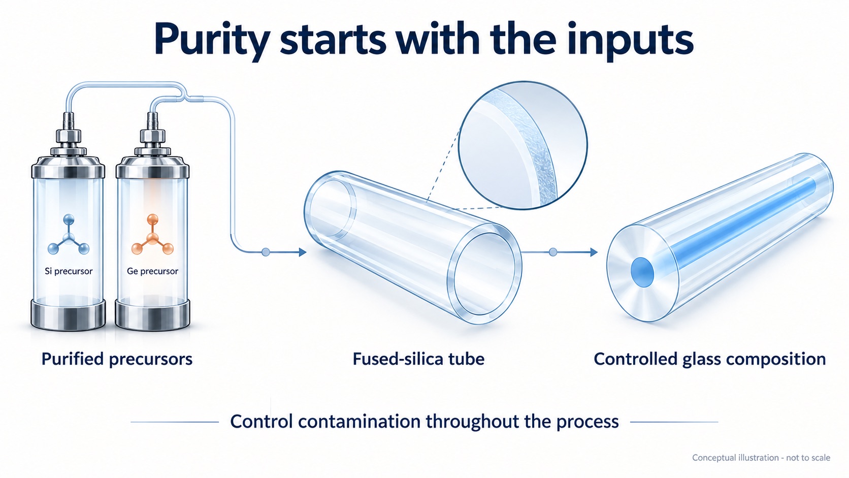
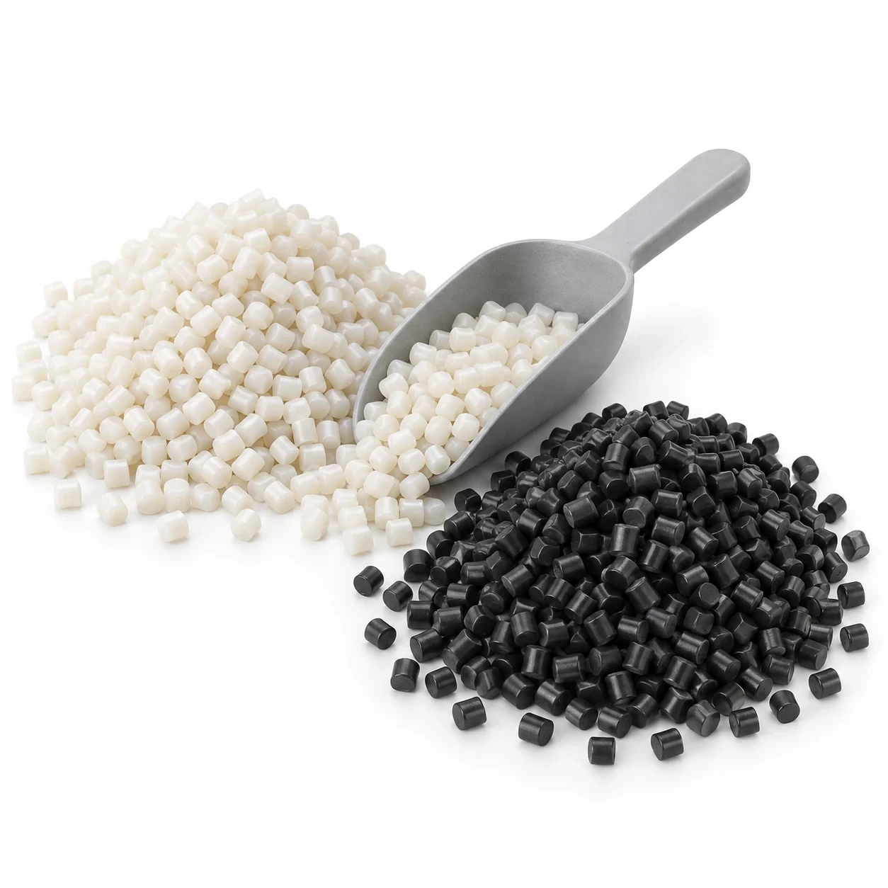
Концептуальная иллюстрация материальных компонентов и контроля загрязнений при подготовке заготовки; не является лабораторной фотографией.
Raw-material selection and contamination control belong in the project’s quality plan. Request material specifications and batch records from the proposed producer, and confirm how nonconforming batches are handled. Обзор производства оптического волокна Heraeus объясняет роль состава материала, геометрии и профиля показателя преломления. Только процент чистоты не определяет эксплуатационные характеристики готового волокна.
Основные химические компоненты
The Описание MCVD Университета имени Лейбница в Ганновере identifies SiCl4, GeCl4 and POCl3 as examples of volatile glass-forming precursors. This is not a mandatory ingredient list for every fiber. For each selected chemical, request the supplier’s grade specification, batch certificate and relevant trace-impurity results; the process owner must approve its suitability.
Germanium doping can raise the refractive index of silica, but the finished fiber must be defined by its complete core-and-cladding design. Do not infer numerical aperture or other optical performance from a germanium concentration alone. Confirm the intended refractive-index profile, dopant formulation and applicable measurements with the preform producer.
Процесс химической реакции
In the MCVD route described by Leibniz University Hannover, precursor vapors pass through a fused-silica tube and an external traversing burner initiates glass formation. Particles deposit on the tube’s inner wall. Deposition, consolidation and tube collapse are distinct stages; one generic reaction-temperature range is not an operating specification for all of them.
Require the process owner to define and qualify the temperature and gas-delivery settings for each stage. The production record should identify the recipe version, measured variables, permitted deviations and response to an excursion. Do not adopt an unsourced temperature-change threshold or flow-stability percentage as proof of complete reaction or acceptable fiber.
Требования к чистоте и испытания
Define impurity limits for the specific input material and intended fiber, not by comparison with another industry. Heraeus’ overview distinguishes hydroxyl-content requirements for UV and infrared transmission, illustrating why application matters. For moisture, metals and other specified impurities, identify the material being tested, concentration units, analytical method and reporting limit. Do not interchange a precursor-gas specification with a finished-glass measurement.
Request the producer’s incoming-material inspection plan, batch certificates and laboratory reports. Ask which analytical methods are used, which contaminants are assessed and how each result is compared with the agreed material specification. Confirm the responsible laboratory and traceability arrangements rather than assuming that the equipment supplier performs these tests.
Используйте эту матрицу для определения документов о приемке входящих материалов. Она не является универсальной спецификацией химической чистоты или лабораторной методикой испытаний.
| Вход для квалификации | Спецификация для получения | Партия или подтверждение поставки | Acceptance decision |
|---|---|---|---|
| SiCl4, если используется | Квалифицированный класс и пределы содержания определённых примесей с единицами измерения | Сертификат партии, соответствующие аналитические результаты и пределы отчетности | Владелец процесса утверждает материал для заданного рецепта |
| GeCl4 или другой прекурсор легирующей добавки, если используется | Выбранный химический состав, марка и пределы примесей для конструкции волокна | Прослеживаемые результаты партии с использованием методов, подходящих для данного материала | Сравните со спецификацией допирующего материала, прошедшей утверждение |
| O2, if used | Требуемая степень очистки газа и предельные концентрации загрязняющих веществ, установленные технологическим процессом | Предоставить сертификат и согласованные проверки на месте использования | Проверьте заданные условия подачи газа |
| Несущие или технологические газы, если используются | Требования к идентификации газа, его чистоте и подаче для конкретного маршрута | Записи поставщика и согласованные проверки состояния линии | Утвердить в соответствии со спецификацией технологической вспомогательной системы |
Рекомендации по хранению и обращению
Before specifying chemical storage, request the current safety data sheets and the chemical supplier’s storage and compatibility requirements. Have the proposed facility design reviewed by qualified personnel. Container materials, atmosphere controls and environmental limits must be established for the actual chemicals and process, not inferred from a generic article.
Require documented procedures for chemical transfer, contamination control, personnel protection and emergency response. Confirm tubing and fitting compatibility, any purge requirements and the applicable training with the responsible process and safety specialists. This overview is not an operating procedure for chemical handling.
Include the required material-handling facilities, inspection work and maintenance in the project scope and cost comparison. Ask for the proposed producer’s contamination-control records, and confirm which safeguards and records are included before comparing quotations.
Как создать стеклянную заготовку?
Качество заготовки напрямую влияет на характеристики волокна. Нестабильное осаждение приводит к изменениям диаметра и оптическим потерям по всей длине волокна.
MCVD deposits glass on the inside wall of a silica tube. OVD builds a porous soot preform around the outside of a target rod before consolidation. These are different fabrication routes; preform dimensions depend on the selected process and equipment.
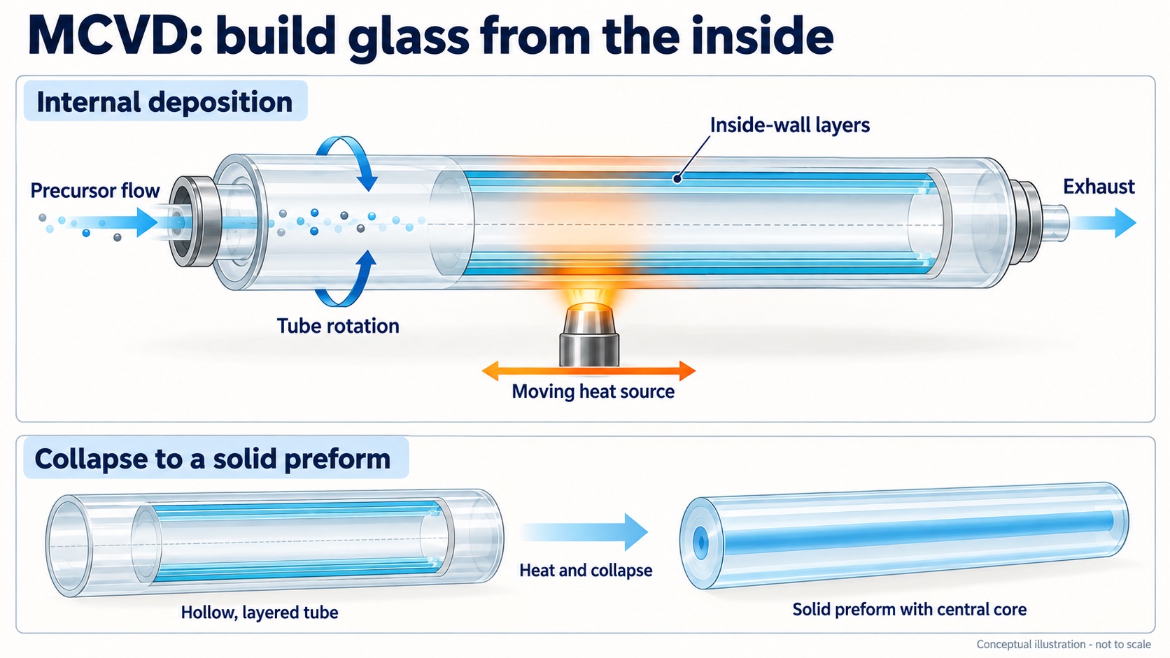
Иллюстрация процесса MCVD: стекло осаждается внутри трубки до её сжатия в сплошную заготовку. Не в масштабе.
For a fiber core manufacturing project, confirm whether preforms will be purchased or fabricated as part of the proposed scope. Request the preform specification, inspection records and compatibility requirements for the drawing equipment. Identify the party responsible for preform production separately from the equipment supplier.
Модифицированный процесс химического осаждения из паровой фазы (MCVD)
In the Процесс MCVD, описанный Ганноверским университетом имени Лейбница, precursor gases flow through a fused-silica tube while an external burner travels along it. Glass particles form and deposit on the tube’s inner wall. The gas composition and deposition conditions control the refractive-index profile; tube dimensions must match the specific process and equipment.
For the proposed MCVD lathe and traversing burner, obtain the qualified tube-size range, rotation and traverse settings, alignment requirements and thermal-control method. Identify whether a reported temperature refers to the flame, tube surface or another target. Treat rotation speed and temperature as equipment- and recipe-specific values rather than universal MCVD settings.
Review the gas-delivery sequence and control arrangement for the proposed MCVD process. Require calibrated flow measurement, a documented deposition schedule and traceable process records. The number of passes, deposited-layer dimensions and permitted flow variation must come from the qualified preform design and demonstrated process, not an assumed standard cycle.
The deposition process creates "soot" – submicron glass particles that form in the hot zone and deposit on the inner wall of the tube. The high temperature consolidates these particles into dense, transparent glass as the burner passes over the deposited soot. The consolidation temperature must be carefully controlled to prevent bubble formation while ensuring complete densification.
Процесс наружного осаждения паров (OVD)
In Объяснение Corning процесса осаждения из внешней паровой фазы, мелкие стеклянные частицы, известные как сажа, накапливаются вокруг внешней стороны мишени или "приманочного стержня". В отличие от MCVD, это осаждение не происходит на внутренней стенке подложки-трубки.
Successive soot layers build outward around the target. The deposition equipment and dopant delivery must follow the intended preform design. This is an external buildup of soot, not deposition within a hollow tube.
Preform size and production output are equipment-specific. Do not use one diameter or length as a universal OVD capability; confirm the qualified preform range with the process-equipment supplier.
В маршруте, описанном компанией Corning, приманочный стержень удаляется до уплотнения. Во время Стадия консолидации OVD, при нагревании пористое сажевое тело превращается в плотное прозрачное стекло. Условия уплотнения должны соответствовать квалифицированному процессу, а не общему температурному режиму.
Контроль качества при изготовлении преформ
For thermal monitoring during preform fabrication, specify the actual measurement target and the instrument suitable for it. Ask the supplier to state calibration, measurement uncertainty and relevant operating limitations. A non-contact temperature reading should not be treated automatically as an accurate flame-temperature or glass-temperature measurement.
Ask the preform producer for refractive-index profile measurements and the stated test method. The report should identify the measured preform, instrument, calibration status and acceptance criteria. Agree how out-of-specification results are handled before the preform is released for drawing.
Include preform diameter, concentricity, straightness and roundness in the agreed dimensional inspection plan. Require the supplier to state the measurement method, units and acceptance tolerances for the specified preform and drawing equipment. Do not adopt an unsourced percentage as a universal limit.
Compare MCVD and OVD proposals against the same intended fiber design and supply scope. Route names alone do not establish fixed core diameters, numerical apertures or attenuation limits. Keep preform inspection separate from acceptance of the fiber drawn from it.
| Элемент для сравнения | Доказательства предложения MCVD | Доказательства по предложению OVD | Acceptance boundary |
|---|---|---|---|
| Маршрут осаждения и поставляемая стадия | Определите трубку-подложку, внутреннее осаждение и этап поставки заготовки | Определите внешнее отложение сажи, уплотнение и этап подачи заготовки | Сравнивайте эквивалентные этапы поставки, а не только метки маршрутов |
| Preform geometry | Чертежи и результаты проверки предложенной заготовки | Чертежи и результаты проверки предложенной заготовки | Укажите, относится ли каждый размер к заготовке или вытянутому волокну, с указанием единиц измерения |
| Профиль показателя преломления и конструкция волокна | Измеренный профиль и целевая спецификация волокна | Измеренный профиль и целевая спецификация волокна | Согласуйте профиль и любой применимый тест числовой апертуры отдельно |
| Концентричность, прямолинейность и круглость | Метод контроля, измеренные результаты и предложенные допуски | Метод контроля, измеренные результаты и предложенные допуски | Применяйте утвержденный чертеж заготовки и план проверки |
| Оптические характеристики готового волокна | Трассируемые результаты, полученные из волокна, вытянутого из предложенной заготовки | Трассируемые результаты, полученные из волокна, вытянутого из предложенной заготовки | Используйте выбранную спецификацию волокна и согласованные условия испытаний, а не общий предел MCVD/OVD |
Оптимизация процессов и устранение неполадок
Require a documented trial plan before changing preform-fabrication parameters. Identify the variables, permitted operating boundaries, measurements and approval responsibilities with the process owner. Keep trial results traceable to the material batch and equipment settings, and record the process owner’s approval.
For a suspected preform defect, first identify the measured feature: interface condition, refractive-index profile or geometry. Compare inspection results with the approved preform design and the corresponding material, deposition and equipment records. A defect name alone does not establish whether contamination, thermal conditions, gas delivery or alignment caused it. Ask the process owner to document the evidence for the proposed cause before changing the recipe.
Request the equipment manufacturer’s preventive-maintenance schedule and calibration requirements. Confirm which burner components, flow controllers and alignment checks are included, who performs each task and what records are required. Agree the maintenance scope before equipment acceptance.
Preform acceptance is one checkpoint, not a guarantee of trouble-free drawing. Link each preform’s inspection record to the drawing run and finished-fiber results so a defect can be investigated across stages. Release the fiber only against the agreed geometry, optical and mechanical requirements.
Какое оборудование необходимо для вытяжки волокна?
Неправильный выбор оборудования приводит к производственным сбоям. Неадекватные системы вытяжки вызывают разрывы волокон, изменения диаметра и дефекты покрытия, которые делают продукт непригодным к использованию.
Specify the drawing system as a complete process: preform feed, furnace, cooling, diameter measurement, coating, curing and take-up. Require the supplier to demonstrate the agreed fiber dimensions and quality at the proposed production speed; a speed figure alone is not an acceptance criterion.
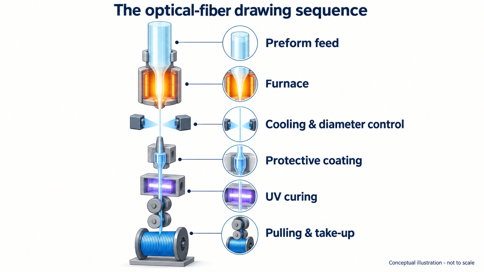
Концептуальная схема последовательности этапов, а не чертёж конкретной поставляемой машины. Не в масштабе.
Coordinate the interfaces between the preform, drawing equipment and coating system before accepting a line proposal. Record the target fiber type, glass-cladding diameter, coated-fiber outer diameter and test conditions so each supplier works to the same product definition.
Конструкция и дизайн чертежной башни
When reviewing a башня для вытягивания волокна, request the supplier’s layout, structural requirements and vibration-control provisions for the proposed configuration. Confirm the required building height, foundations, service access and utility interfaces from the actual equipment drawings rather than assuming a standard tower size.
Башня вмещает несколько зон, каждая из которых выполняет определенную функцию в процессе вытяжки. Верхняя секция содержит механизм подачи преформ и печь. Средняя секция обеспечивает пространство для охлаждения волокна и измерения диаметра. Нижняя секция вмещает систему нанесения покрытия, печи отверждения и приемное оборудование.
Ask the drawing-equipment and coating suppliers to specify the required cleanliness, temperature, humidity and ventilation conditions. Record operating and shutdown requirements in the utility schedule, together with monitoring methods and acceptance limits. Assign responsibility for establishing and maintaining these conditions.
Системы высокотемпературных печей
Confirm the furnace heating technology, usable hot zone, preform-size range and qualified operating window with the equipment manufacturer. Furnace dimensions and maximum temperature must come from the proposed equipment specification, not a generic production-line example.
Request the furnace supplier’s temperature-measurement and control specification, including sensor type, calibration, measurement uncertainty and demonstrated control performance. Distinguish a stated controller resolution from verified furnace stability, and agree the acceptance test for the supplied system.
Confirm furnace-gas requirements with the furnace manufacturer and responsible process engineer. The utility specification should identify gas type, quality, flow requirements, monitoring and safety provisions for the actual system. Do not use a generic oxygen limit or gas selection as an approved operating recipe.
For the preform-feed system, request the supported preform dimensions and mass, feed range, positioning performance and coordination with draw control. Agree a test using the intended preform rather than assuming a universal positioning tolerance.
Измерение и контроль диаметра
Specify what each gauge measures: bare-glass outer diameter, coated-fiber outer diameter or another defined feature. Request the instrument’s measurement range, accuracy, repeatability, sampling rate and calibration requirements. Do not treat resolution, response time and achieved production tolerance as interchangeable specifications.
Draw speed is one control variable used to regulate bare-glass diameter, but it interacts with preform feed, thermal conditions and tension. Confirm which variables the proposed controller actually adjusts, where the diameter is measured and how transport delay is handled. Require a recorded trial showing diameter and tension together during steady running and approved speed changes; a simple ‘speed up when thick’ rule is not a complete control specification.
Прогнозирующее и обучающееся управление следует рассматривать как конкретные предлагаемые функции, а не как стандартные особенности каждой линии вытяжки. Например, в научной статье Динамическое управление процессом производства оптоволокна с использованием глубокого обучения с подкреплением reports tests on a compact fiber-drawing system. It does not establish deployment or performance on the production line being quoted. Request the actual control architecture, operating limits and acceptance demonstration for any such claim.
| Параметр | Укажите в предложении | Основание для принятия | Доказательства для запроса |
|---|---|---|---|
| Furnace operation | Технология нагрева, полезная горячая зона и рабочее окно | Квалифицированные настройки для выбранной заготовки | Технические характеристики оборудования и зарегистрированные условия испытаний |
| Диаметр стеклянной оболочки | Наружный диаметр голого стекла, отличный от диаметра сердцевины | Целевое значение и допуск в выбранной спецификации волокна | Данные калиброванного измерительного прибора и согласованный метод инспекции |
| Скорость рисования | Согласованная скорость производства для указанного волокна | Качество, продемонстрированное на этой скорости | Протокол испытаний, связывающий скорость с геометрией и оптическими результатами |
| Наружный диаметр покрытого волокна | Диаметр по отверждённому покрытию, а не радиальная толщина покрытия | Целевое значение и допуск для выбранной конструкции покрытия | Результаты измерения диаметра и концентричности согласно согласованному испытанию |
Системы нанесения покрытий
Система покрытия наносит защитные полимерные слои на голое стекловолокно сразу после формирования. Покрытие должно наноситься концентрически и равномерно, чтобы предотвратить потери на микроизгибы и обеспечить механическую защиту. Большинство систем используют аппликаторы под давлением, которые наносят жидкий материал покрытия вокруг волокна.
The primary coating is the polymer layer next to the glass. Confirm its material, cured outer diameter and acceptance requirements in the qualified coating design. Do not assume a fixed radial thickness for every optical-fiber product.
The secondary coating surrounds the primary layer. Distinguish its outer diameter from the thickness of either layer. For concentric circular layers, total radial coating thickness = (coated-fiber outer diameter – glass-cladding diameter) / 2. This relation alone does not determine how the thickness is divided between primary and secondary coatings.
Для примера, относящегося к конкретному продукту, Corning’s SMF-28 Ultra product sheet, July 2025, page 2 lists a glass-cladding diameter of 125.0 ± 0.7 μm and coated diameters of 242 ± 5 μm or 200 ± 5 μm, depending on the option. Using nominal diameters gives combined radial coating thicknesses of 58.5 μm and 37.5 μm respectively. These are calculated examples for that product, not universal coating recipes or HONGKAI equipment guarantees.
Request the proposed coating-concentricity measurement method and die-alignment procedure, with acceptance limits tied to the specified fiber and coating system. Keep geometry checks and optical-performance tests separate: a concentricity result alone does not establish the fiber’s polarization-mode-dispersion performance.
Системы УФ-отверждения
Системы ультрафиолетового отверждения полимеризуют жидкие акрилатные покрытия в твердые защитные слои. Процесс отверждения должен быть полным и равномерным, чтобы обеспечить надлежащие свойства покрытия. Неполное отверждение может привести к липким поверхностям и плохим механическим свойствам.
Отверждение волоконного покрытия не ограничивается одной технологией ламп. Excelitas’ UV-LED fiber-curing application note describes conventional arc/microwave lamp systems and UV LED systems, and stresses testing the coating with the selected light source. Ask the coating and equipment suppliers to qualify the spectral match, exposure, optical arrangement and thermal conditions at the proposed line speed; lamp layout alone does not prove uniform cure.
If the proposed curing system uses nitrogen inerting, obtain the required gas specification, chamber conditions, monitoring and alarm limits from the coating and curing-equipment suppliers. Verify the cured coating against an agreed test method. Nitrogen supply alone is not evidence that the coating has reached its required cure state.
Системы контроля натяжения и натяжения
Tension control throughout the drawing process is essential for consistent fiber properties. Excessive tension can cause fiber breaks or diameter variations, while insufficient tension can lead to loose winding and handling problems. Agree the drawing-tension range, force units, measurement method and acceptance conditions for the actual fiber and drawing system.
For the capstan system, request the drive-control specification, fiber-contact surface details and maintenance requirements. Ask the supplier to demonstrate the proposed speed-control performance and fiber-handling results under agreed test conditions rather than relying on an unsupported accuracy figure.
Take-up systems wind the finished fiber onto spools for storage and shipping. The winding pattern must prevent fiber damage while allowing easy unwinding for subsequent processing. Confirm the traverse mechanism, winding pattern and take-up tension requirements with the supplier, then verify the result using the agreed spool and fiber specification.
If the take-up uses a dancer, confirm its loading method, usable travel, position feedback and connection to reel-speed control. Verify winding tension during acceleration, steady running and spool build-up with the intended fiber and reel. A dancer’s presence does not guarantee constant tension, and take-up tension must not be confused with the tension measured in the hot drawing zone.
Как вы контролируете качество волокна в процессе производства?
Контроль качества предотвращает дорогостоящие производственные дефекты. Без надлежащего контроля целые производственные циклы могут не соответствовать требованиям спецификации, что приводит к значительным материальным и временным потерям.
Use a quality plan that separates inline process measurements from optical and mechanical acceptance tests. Define each measured feature, test method, inspection frequency and acceptance limit; inline diameter feedback alone does not verify every finished-fiber requirement.
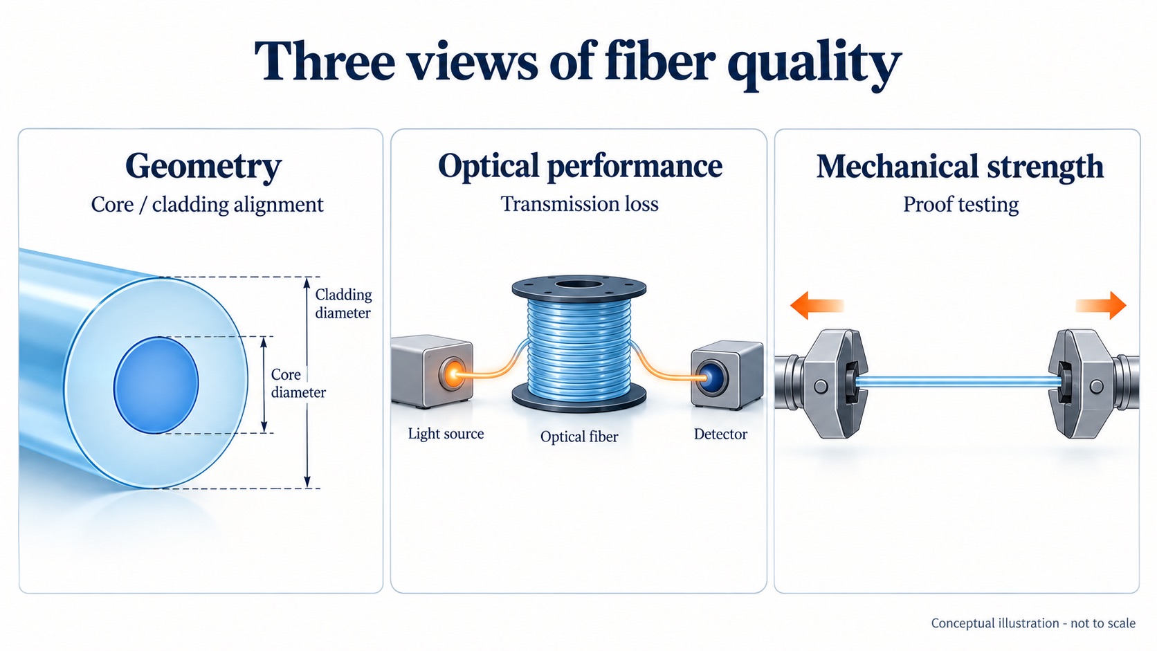
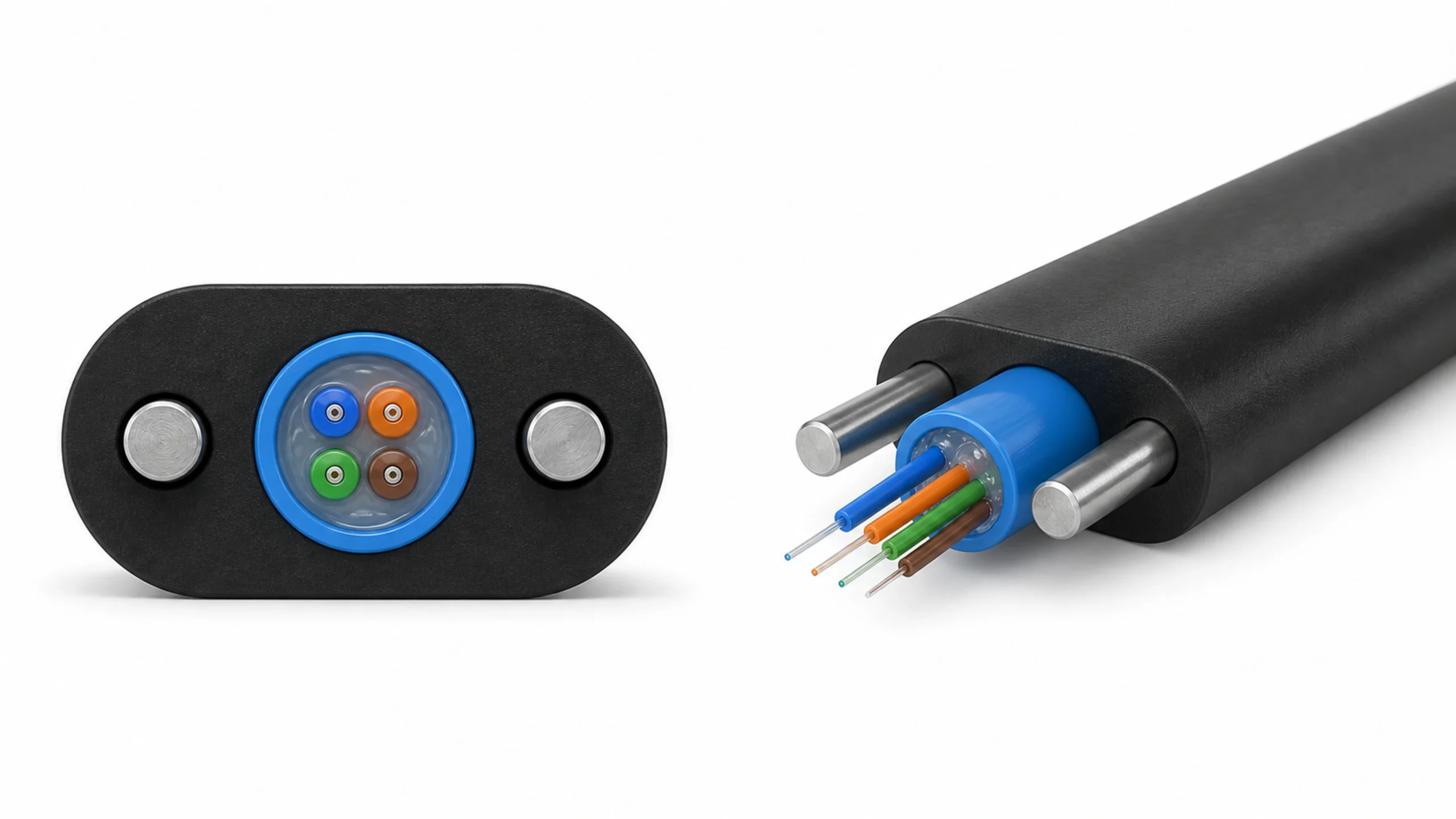
Концептуальная иллюстрация геометрических, оптических и механических проверок; измеренные результаты испытаний не приведены.
Define the fiber-production quality plan before accepting the equipment. Identify the measurements, inspection frequency, acceptance criteria and responsibility for nonconforming material at each stage. Request sample records from the proposed producer and agree which checks are included in the supplied scope.
Мониторинг процессов в реальном времени
For each inline measurement, record the sensor principle, accuracy, sampling rate, filtering and position on the line. Ask the supplier to demonstrate which defects the complete measurement-and-control system can detect at the proposed draw speed. Do not infer a minimum detectable defect length or closed-loop response from the gauge resolution alone.
For coating inspection, ask whether the proposed instrument reports coated outer diameter, concentricity or individual-layer geometry. An outer-diameter reading alone does not establish the separate primary and secondary layer thicknesses. Document which features are measured, the calibration method and how the results are checked against the selected coating design.
Не предполагайте, что каждое измерение натяжения при протяжке использует тензодатчик. Описание SIKORA измерения натяжения оптического волокна discusses vibration-based measurement and a birefringence-based optical method. Confirm the proposed instrument, measurement location, units and validation procedure. Define separately whether its signal is displayed, logged, used for an alarm or connected to an automatic control loop; measurement alone does not prove automatic break prevention.
List the thermal and environmental measurements actually included in the proposed line, such as fiber temperature before coating and conditions in the coating or curing area. Identify each measurement target, sensor, logging interval and alarm boundary. Verify any thermal-imaging or contamination-monitoring function explicitly rather than assuming it is supplied with the tower.
Тестирование оптических свойств
Выберите метод измерения затухания, соответствующий типу волокна и требуемому отчету. The IEC 60793-1-40:2024 attenuation-method overview lists cut-back, insertion-loss and backscattering methods, as well as spectral modelling with a narrower scope. Record the selected method, test wavelengths, launch conditions, sample identification and acceptance limits; do not assume every production test uses cut-back.
Для многомодового волокна определите требуемый показатель полосы пропускания и условия запуска. IEC 60793-1-41:2024 distinguishes time-domain, frequency-domain and DMD-derived overfilled-launch bandwidth methods. IEC 60793-1-49:2018 describes DMD characterization of graded-index multimode fiber for bandwidth assessment under different launch conditions. Do not describe a DMD report as a direct refractive-index-profile measurement. Ask the laboratory to identify the fiber category, wavelength, method and reported bandwidth metric.
Различайте измеренную числовую апертуру и значение, рассчитанное с использованием показателей преломления. The IEC 60793-1-43:2015 overview covers specified multimode-fiber categories and distinguishes far-field numerical aperture from theoretical numerical aperture. Ask the laboratory to state the applicable fiber category, sample length, measurement threshold and uncertainty. Do not use a numerical-aperture result as a substitute for a required single-mode cutoff-wavelength test.
Для одномодового волокна укажите метод испытания диаметра модового поля (MFD) и длину волны, на которой приводятся результаты, совместно. IEC 60793-1-45:2024 addresses MFD measurement. Compare results with the selected fiber specification at the same stated wavelength; do not treat an MFD value without its wavelength as a complete acceptance requirement.
Испытание механических свойств
Proof testing applies a specified tensile stress to screen fiber for weak sections. As one documented example, section 1.4 of Технические характеристики волокна Corning PGSF001 specifies a minimum of 100 kpsi (approximately 0.69 GPa) for the fibers covered by that document. Here, 100 kpsi means 100,000 psi. Use the applicable fiber specification and test procedure for the product being manufactured.
Coating adhesion testing verifies that the polymer coatings bond properly to the glass surface and to each other. Poor adhesion can lead to coating delamination during handling or environmental exposure. Request the applicable coating-adhesion and stripping test procedures, reported results and acceptance criteria from the fiber producer.
Испытание на изгиб оценивает устойчивость волокна к потерям при макроизгибе и микроизгибе. Испытания на макроизгиб наматывают волокно вокруг оправок различных диаметров для имитации условий монтажа. Испытания на микроизгиб применяют контролируемое боковое давление для имитации эффектов производства кабеля и стрессов окружающей среды.
Экологические испытания подвергают образцы волокон воздействию циклической температуры, влажности и химических сред, которые могут встретиться в процессе эксплуатации. Эти испытания помогают прогнозировать долгосрочную надежность и выявлять потенциальные виды отказов до того, как они произойдут в полевых условиях.
Use the following planning matrix to agree the product-specific quality plan. A measurement standard defines how a test is performed; it is not, by itself, a universal product limit or a sampling plan. Adapt the wavelength rows to the selected fiber rather than applying them to every fiber type.
| Test parameter | Метод указания | Покрытие или выборка по согласованию | Основание для принятия |
|---|---|---|---|
| Attenuation at 1310 nm, if specified | Applicable method under IEC 60793-1-40:2024 | Определено в плане качества продукции | Максимальные потери для выбранного волокна на данной длине волны |
| Attenuation at 1550 nm, if specified | Applicable method under IEC 60793-1-40:2024 | Определено в плане качества продукции | Максимальные потери для выбранного волокна на данной длине волны |
| MFD одномодового волокна на указанной длине волны | Applicable method under IEC 60793-1-45:2024 | Определено в плане качества продукции | Номинальное значение и допуск на той же длине волны |
| Контрольный тест | IEC 60793-1-30:2010 fibre proof-test procedure | Требуемая протестированная длина и прослеживаемые записи бухты | Уровень напряжения и правила приемки из выбранной спецификации волокна |
| Наружный диаметр покрытого волокна | Согласованный метод испытаний на размеры | Определено в плане качества | Целевое значение и допуск из выбранной спецификации волокна/покрытия |
Статистический контроль процессов
Statistical process control (SPC) can help identify changes in recorded process measurements. Руководство NIST по контрольным картам explains that both points outside control limits and non-random patterns can warrant investigation. Control limits describe process behavior; they are not the product’s specification limits. A stable process can still produce nonconforming fiber. For the proposed quality system, identify the measured feature, chart type, sampling method, investigation rules and responsible person. Confirm whether alerts are actually implemented; a chart alone does not prevent defects or release a spool for shipment.
Перед интерпретацией Cp или Cpk убедитесь, что процесс стабилен и что данные и метод расчета подходят. Обзор процесса NIST по оценке производственных возможностей compares stable-process variation with specification limits and states the normal-distribution assumption of the conventional indices. Cp compares specification width with process spread; Cpk also accounts for an off-center process mean. Ask for the underlying measurements, units, sampling period, specification limits and statistical assumptions, not just an index on a dashboard. Agree any required capability criterion for the project; do not substitute an unsourced universal threshold for the fiber’s acceptance tests.
Design of experiments (DOE) techniques help optimize process parameters and understand the relationships between different variables. For any proposed optimization trial, agree the factors, response measurements and permitted operating boundaries with the process owner, and require a traceable report of the results.
Correlation analysis helps identify relationships between different measurements that might not be obvious. Treat a measured correlation as a finding to investigate, not proof of a causal relationship or a guaranteed process improvement.
Автоматизированные системы качества
For an automated quality-control proposal, require a list of measured inputs, controlled outputs, alarm actions and operator responsibilities. Ask the supplier to demonstrate each promised feedback or predictive function on the proposed system. Do not assume that machine-learning prediction or automatic defect prevention is included in a standard drawing line.
Specify which process and test data will actually be recorded, with timestamps, length or spool references, retention and export requirements. Check a sample production record before acceptance; an automation interface does not establish that every quality parameter is captured or traceable.
Ask the supplier to demonstrate how an out-of-specification segment is identified, located, segregated and documented. State whether handling requires stopping, cutting, transfer or later rewinding, and define the restart and retest procedure. Do not assume defective fiber can be removed while drawing continues without interruption.
If ERP or other factory-system integration is required, define the data fields, spool identifiers, interfaces, access rights and responsibility for failed transfers. Test a sample record from measurement through export and retrieval before acceptance. An available interface does not by itself establish end-to-end traceability or regulatory compliance.
Каковы распространенные проблемы производства и их решения?
Производственные проблемы могут остановить целые производственные линии. Нерешенные проблемы приводят к повреждению оборудования, отходам материалов и невыполнению обязательств по поставкам, что подрывает отношения с клиентами.
Обрывы волокна, изменения диаметра и дефекты покрытия требуют систематического устранения неисправностей и применения протоколов профилактического обслуживания для поддержания стабильного качества продукции.
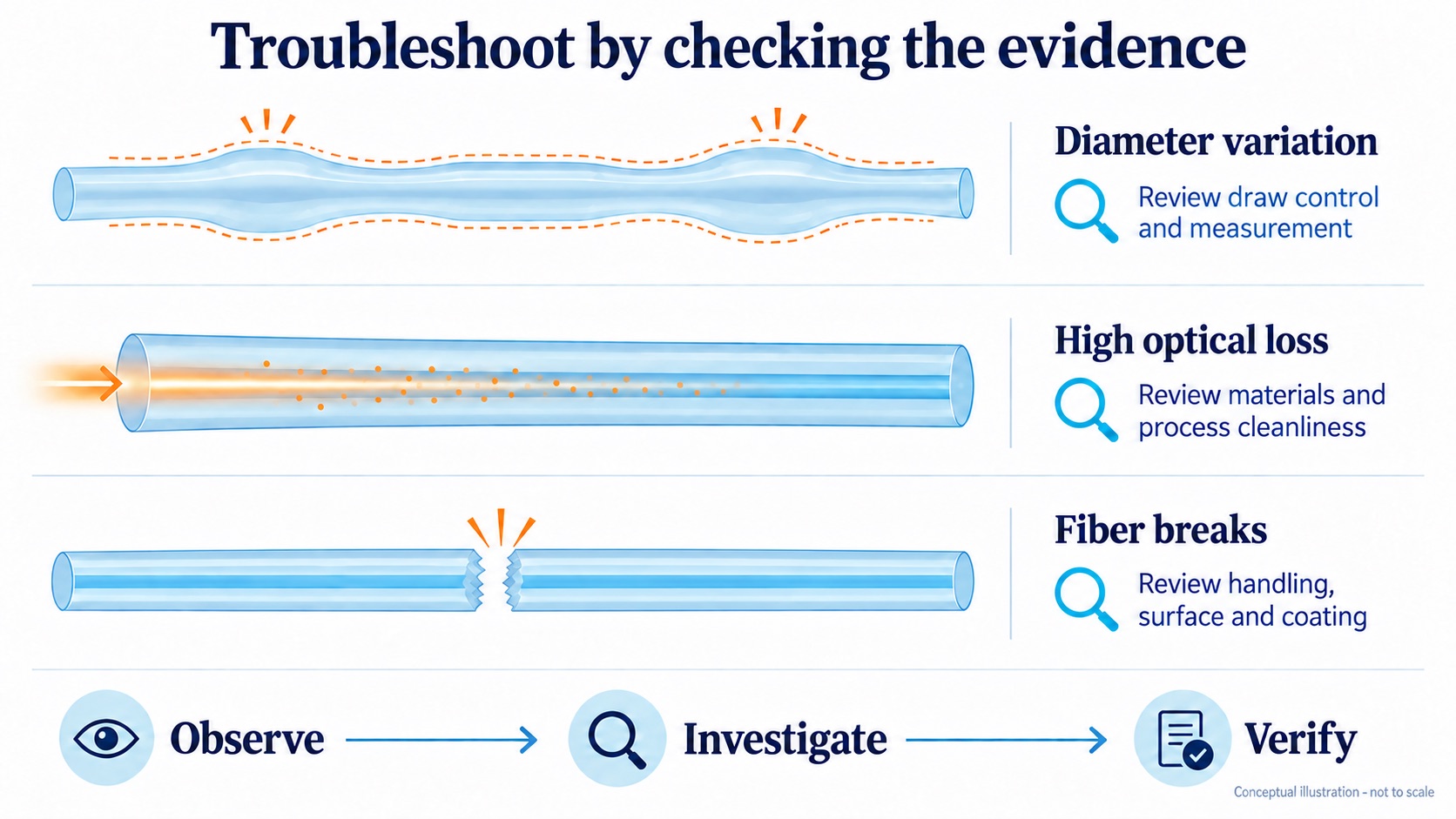
Иллюстрация для концептуальной диагностики неисправностей. Перечисленные проверки являются подсказками для расследования, а не подтверждёнными причинами или гарантированными решениями.
Use production records, alarms, inspection results and supplier procedures to investigate fiber-manufacturing problems. Establish the observed symptom and operating conditions before proposing a cause. Follow the applicable manufacturer’s safety and maintenance instructions before making adjustments.
Проблемы с разрывом волокна
Fiber breaks represent one of the most common and disruptive problems in fiber manufacturing. These breaks can occur at any point in the drawing process, from the furnace exit to the take-up reel. Understanding the different types of breaks and their causes is essential for effective troubleshooting.
For a break near the furnace exit, preserve the time, preform identity, break location and preceding thermal, feed and tension records. Review relevant preform inspections and furnace alarms with the process owner. Do not diagnose ‘thermal shock’ or contamination solely from the break location. Inspection of the furnace or hot-zone components must follow the manufacturer’s safe shutdown and maintenance procedure.
For a suspected tension-related break, compare the tension trace with capstan speed, dancer position, reel events and the recorded break time. First confirm the measurement location and signal validity. A tension change after the fiber has broken may be a consequence, not its cause. Have qualified personnel review the evidence before changing control settings or inspecting the fiber path.
If breaks appear near coating or downstream handling equipment, retain representative samples and record their position relative to dies, guides, capstan and take-up. Check the applicable coating-geometry, cure, adhesion and mechanical-test results with the suppliers. Neither an eccentric coating nor a tacky surface alone proves the failure mechanism; compare the findings with the actual break evidence.
Проблемы контроля диаметра
Изменения диаметра могут сделать волокно непригодным для точных приложений. Эти изменения могут происходить на коротких расстояниях (микроизменения) или на больших расстояниях (макроизменения), каждое из которых требует различных подходов к устранению неполадок.
Compare a diameter excursion with the identified preform, feed position and preform inspection records, but do not assume that a preform dimension transfers directly into the finished-fiber diameter. The drawing process and its control response also matter. Confirm the measured feature and units before comparing preform geometry, glass-cladding diameter or core geometry.
When investigating thermal conditions, compare the diameter trace with the furnace setpoint, measured temperature, power and relevant utility records. Distinguish the controller reading from the actual temperature of the glass. Check timing and measurement limitations before assigning a thermal cause or approving a recipe change.
For a suspected control problem, compare commanded and measured speed with the raw and filtered diameter signals. Ask the controls specialist to check sensor validity, delay, output limits and interactions between loops. Do not begin with arbitrary PID changes; use the approved trial procedure and retain before-and-after records.
If the diameter signal is periodic, compare its timing with known equipment cycles and environmental measurements. Check whether the pattern is present in an independent measurement or is an artefact of the gauge, filtering or sampling. A frequency match is an investigation lead, not proof that vibration or airflow caused the product defect.
Используйте эту диагностическую матрицу для сбора доказательств до выбора метода вмешательства. Её проверки не являются подтверждёнными причинами или универсальными инструкциями по эксплуатации.
| Observed symptom | Доказательства для сохранения | Первичная проверка с ответственным специалистом | Recovery evidence |
|---|---|---|---|
| Разрывы волокон | Место обрыва, время, идентификатор заготовки/бухты и предшествующие сигналы | Проверьте график натяжения и сопоставьте его с тепловыми, подающими и манипуляционными событиями | Утвержденный перезапуск с требуемыми геометрическими, механическими и оптическими результатами для затронутого материала |
| Изменение диаметра | Необработанные данные измерения, единицы измерения, записи скорости/подачи и временные метки событий | Проверьте точность измерительного прибора и отделите артефакты измерения от изменений в процессе до настройки | Согласованный допуск по диаметру, подтвержденный в условиях задокументированных испытаний |
| Дефекты покрытия | Samples, material lot, coating geometry, curing and handling records | Check the specified geometry and cure tests; review alignment and exposure only within supplier procedures | Results meeting the selected coating specification, with traceability to the trial |
| Увеличение затухания | Метод испытания, длина волны, идентификация образца, условия запуска и история обращения | Confirm the test setup and repeatability before investigating material or process causes | Repeatable results meeting the fiber specification and documented disposition of affected spools |
Проблемы с нанесением покрытия
Дефекты покрытия могут влиять как на оптические, так и на механические свойства готового волокна. Эти проблемы часто развиваются постепенно, что делает раннее обнаружение необходимым для предотвращения большого количества дефектной продукции.
For a coating-dimension change, establish whether the measurement concerns total coated diameter, an individual layer or concentricity. Compare the validated trace with coating pressure, material temperature, lot history and die inspection records. The rate of change alone does not distinguish die wear from pressure, material or measurement issues.
When coating concentricity is outside the agreed limit, inspect fiber centering, die alignment and the measurement setup using the supplier’s procedure. Record the geometry results and perform any required optical tests separately. Do not diagnose polarization-mode dispersion from coating eccentricity alone.
For a suspected cure problem, record the coating formulation and lot, light-source type, exposure conditions, line speed and any specified inerting conditions. Compare the agreed cure and mechanical tests with the qualified coating process. A tacky surface or brittle sample is a symptom, not a complete diagnosis. Do not prescribe more UV exposure or attribute cracking to excessive cure without the coating supplier’s assessment.
When adhesion or stripping results are out of specification, confirm the test method and sample conditioning before comparing material, surface-handling and cure records. Ask the coating supplier to assess retained samples. Record the evidence and disposition rather than assuming contamination or material degradation is the cause.
Систематический подход к устранению неполадок
Effective troubleshooting requires a systematic approach that considers all possible causes and uses data to guide the investigation. Start by reviewing when the problem began, the recorded operating conditions and any changes made before the symptom appeared.
Анализ данных играет решающую роль в выявлении проблемных моделей. Графики тенденций могут выявить постепенные изменения, которые могут быть неочевидны из отдельных измерений. Корреляционный анализ может выявить связи между различными параметрами, которые указывают на первопричины.
Use batch comparisons to narrow the investigation, not to assign blame. If an excursion occurs with one preform batch, check whether recipe, operator, instrument, equipment or environmental conditions also changed. Compare equivalent runs and record which alternative explanations the evidence actually excludes.
A fishbone diagram or five-why review can organize hypotheses, but the diagram is not proof of root cause. Assign an owner to each check, document supporting and conflicting evidence, and verify the approved corrective action against the agreed acceptance criteria. Continue monitoring after restart; one successful trial does not guarantee that the problem cannot recur.
Стратегии профилактического обслуживания
Программы профилактического обслуживания помогают избежать многих распространенных проблем на производстве, устраняя потенциальные проблемы до того, как они приведут к сбоям в производстве. Эти программы должны основываться на рекомендациях производителей оборудования, исторических данных об отказах и требованиях к процессу.
Плановые мероприятия по техническому обслуживанию включают регулярную калибровку измерительных систем, замену изношенных компонентов и очистку критических зон. График технического обслуживания должен учитывать как временные, так и эксплуатационные интервалы для оптимизации надежности оборудования.
Методы мониторинга состояния могут выявлять развивающиеся проблемы до того, как они приведут к отказам. Анализ вибрации может обнаружить износ подшипников или проблемы с выравниванием. Тепловидение может обнаружить электрические проблемы или проблемы с системой охлаждения. Анализ масла может выявить внутренний износ в гидравлических или смазочных системах.
Управление запасами запасных частей гарантирует, что критически важные компоненты будут доступны, когда это необходимо для обслуживания или экстренного ремонта. Инвентарь должен включать как элементы планового обслуживания, так и необходимые запасные части, которые могут привести к длительному простою, если их не будет.
Программы обучения гарантируют, что операторы и обслуживающий персонал понимают надлежащие процедуры и могут распознавать ранние признаки развивающихся проблем. Регулярные обновления обучения помогают поддерживать навыки и внедрять новые методы или технологии.
Системы документирования отслеживают мероприятия по техническому обслуживанию, историю проблем и тенденции производительности оборудования. Эта информация помогает оптимизировать графики технического обслуживания, выявлять повторяющиеся проблемы и поддерживать непрерывные усилия по улучшению.
Заключение
Успешное производство сердечников волокон требует точного контроля материалов, оборудования и процессов на протяжении всей производственной цепочки.
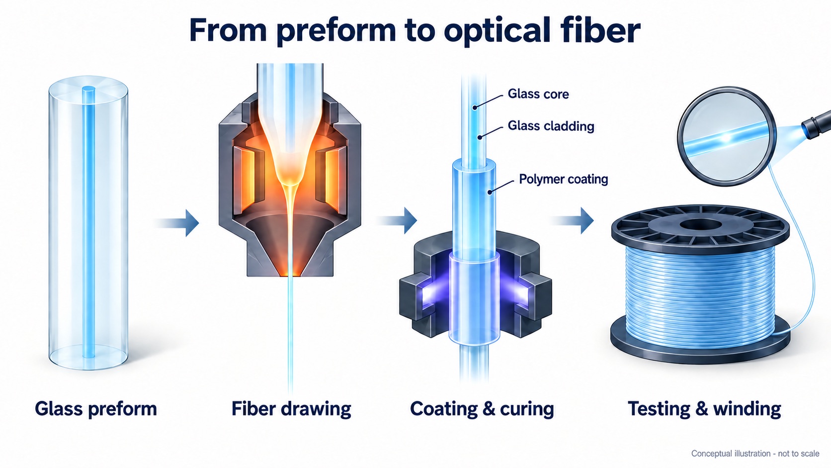
Концептуальная иллюстрация основных этапов производства оптического волокна; не в масштабе.

 English
 हिन्दी
 فارسی