


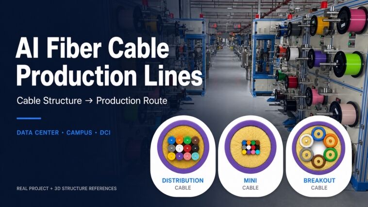
AI is increasing the speed, density and physical size of data-center networks. However, an AI project does not use one universal product called an “AI fiber optic cable.”
AI infrastructure normally needs several cable families: indoor high-density cables for data halls, OS2 single-mode cables for campus and data-center interconnects, and protected outdoor cables for duct, armored or aerial routes. Short links may also use OM4 multimode cable, while some very short server links use copper instead of fiber. The correct production line is selected from the finished cable structure, not from the word “AI.” A cable manufacturer must therefore define the network location, cable drawing, fiber count, installation environment and required capacity before buying equipment.

HONGKAI 3D reference configuration: an HK-50 loose-tube production line with 12 fiber pay-off positions for the secondary-coating stage.
IEEE has already standardized 800 Gb/s Ethernet optical links over both multimode and single-mode fiber, so “800G” does not by itself identify one cable construction.1 The optical module, reach, link budget, connector interface and installation route still decide whether a project uses OM4, OS2, duplex, parallel-fiber, loose-tube or another design.
This guide maps the main AI-network locations to the cable structures and production stages a cable factory may need. Every route is a reference route; the final equipment model, tooling, quantity and acceptance plan must be confirmed from the approved cable drawing.
What Fiber Optic Cables Does AI Infrastructure Actually Need?
AI infrastructure normally uses four product groups: indoor patching and distribution cables, high-density data-hall trunks, campus or data-center-interconnect cables, and protected outdoor backbone cables. OM4 multimode and OS2 single-mode can both appear inside a data center, depending on the optical interface and distance. OS2 single-mode is normally the starting point for longer campus and interconnect routes. Fiber count and cable protection then change with the network design and installation environment.
| AI network location | Typical cable products | Main manufacturing direction |
|---|---|---|
| Inside a rack or pod | Duplex patch cable, parallel-fiber trunk, or no optical cable when a passive copper link is specified | Indoor base cable plus separate connector assembly where required |
| Row and data hall | Distribution cable, breakout cable, simplex/duplex base cable, high-density trunk | Tight buffer or another approved indoor cable process, reinforcement and outer jacket |
| Building-to-building or DCI | OS2 loose-tube cable, micro cable, high-fiber-count cable, optional ribbon design | Coloring, loose tube or ribbon process, core formation, protection and sheathing |
| Duct, direct-buried or aerial route | Central-tube, stranded loose-tube, armored cable, ADSS or another route-specific design | Outdoor cable line with the required water blocking, strength and environmental protection |
These names describe different things. OM4 and OS2 describe optical cabling categories. G.652.D and G.657.A describe single-mode fiber characteristics.2 Tight buffer, loose tube, ribbon, armor and ADSS describe cable structures that affect the equipment route. MPO/MTP and LC describe connector interfaces and do not define the base cable by themselves.
The HONGKAI fiber optic cable production line guide shows how finished cable structures lead to different process modules. A published Open Compute Project architecture also illustrates an important limit: passive copper can remain inside an AI pod, while optical links are used when the connection leaves that local zone.3 A factory should not assume that every AI server connection becomes a fiber order.
Recent HONGKAI customer enquiries and project discussions for AI data centers in China have included both indoor multi-fiber breakout constructions and compact mini cable. For screening, compare the cross-section and check whether every fiber or subunit has its own protective jacket; the two names are not interchangeable. These enquiries are company-specific experience, not a market-share claim or evidence of a wider China or global industry trend.
Note: The useful sales question is not “Which AI cable is popular?” but “Which part of the AI network will this finished cable serve?”
Which Production Line Makes Indoor AI Data-Center Cables?
Indoor AI data centers do not use one universal “micro cable” or “breakout cable.” Distribution cable, mini cable, breakout cable and ribbon cable are separate constructions and do not use one interchangeable production line. A GJFJV distribution route can use the HK-30 tight buffered production line before the configured HK-50 GJFJV stage; a compact mini cable uses its own upstream core or subunit process and an HK-50 PLC+IPC mini-cable sheathing configuration; a true breakout cable first forms individually protected subcables before assembly and final sheathing. Outdoor air-blown micro cable for campus or DCI ducts is another loose-tube or ribbon product with a different equipment route.

HONGKAI 3D equipment model: the complete HK-30 line produces the tight-buffered fiber element used by many indoor cable structures.
HONGKAI 3D structure reference: twelve color-coded tight-buffered fibers share a strength-yarn layer and one outer jacket. Fiber type, yarn material, jacket compound and flame rating are confirmed per cable specification.
Decision criterion: A distribution cable normally groups buffered fibers under one common cable jacket. A mini cable uses a separate compact core and sheathing design to reduce the finished construction, while a true breakout cable contains individually protected subcables before the final outer jacket. These three production routes must be quoted separately, even when all three products are installed inside the same data center. The word “breakout” may also describe a port-splitting assembly, so the buyer’s cross-section and finished connector map must be checked before assigning the cable-making route.4
- HONGKAI 3D structure reference: six individually jacketed single-fiber subcables are assembled beneath a common outer jacket. The drawing explains breakout construction; it does not identify connector type or project use.
-
::flow
01 · Prepare|Load qualified coated fiber
Confirm the incoming fiber specification, reel condition and pay-off tension before extrusion.
02 · Tight buffer|Apply the buffer layer
The HK-30 process adds the specified tight-buffer material and controls cooling, diameter and take-up.
03 · Build cable|Add the required strength
Combine the buffered elements and add aramid yarn or other reinforcement only when the finished drawing requires it.
04 · Finish|Jacket, test and coil
- Extrude the outer jacket, print and measure the cable, then complete the agreed optical and dimensional tests.
-
::
| Finished indoor product | Cable-making stages | Separate work after cable making |
|---|---|---|
| Simplex or duplex base cable | Tight buffer, reinforcement, outer jacket and coiling | Connector termination when sold as a patch cord |
| Multi-core distribution cable | HK-30 tight buffer → fiber gathering or stranding → aramid reinforcement → configured distribution-cable sheathing stage | Connectorization or fan-out when required |
| Breakout cable | HK-30 tight buffer where required → individual simplex or subunit cable formation → subcable assembly → final outer jacket | Direct termination or connector assembly according to the order |
| Compact indoor mini cable | Approved fiber or subunit input → compact core formation → dedicated HK-50 PLC+IPC mini-cable sheathing configuration | The mini-cable cross-section decides its upstream route; do not substitute the distribution-cable line |
| GJFJV indoor cable | HK-30 tight buffer, subunit/core formation, strength-member application and outer jacket according to the approved design | Final connector or packaging work according to the order |
| GJFV indoor cable using colored fiber directly | Colored-fiber pay-off, strength-member application and outer jacket | Add HK-30 only when the approved structure requires a tight-buffer element |

Real production footage: HONGKAI HK-50 PLC+IPC mini cable sheathing equipment producing indoor multi-fiber cable for a China AI data center project.
The production footage confirms that the HK-50 PLC+IPC mini cable sheathing line is used for the compact core and outer-jacket stage. The video alone does not prove that the finished product is a classic breakout construction, because the individual subunit jackets and complete cross-section are not visible. Line speed, cable diameter and upstream process must come from the approved product drawing and project agreement.
HONGKAI 3D structure reference: twelve color-coded fibers form a compact bundle inside a strength-yarn layer and one outer jacket. The illustration is not a verified cross-section of the production footage above and does not show individually jacketed breakout subcables.
The HONGKAI GJFJV cable production route uses HK-30 tight buffering before the HK-50 GJFJV stage. The HONGKAI GJFV route can begin with approved colored fiber instead, while the patch-cord base-cable line uses tight-buffered elements. In this article, “mini cable” means a compact indoor multi-fiber cable; it should not be confused with an outdoor duct or air-blown micro cable. Material choice and flame performance must still follow the buyer’s specification and the rules of the target market.
Note: An indoor-cable quotation should separate tight buffering, subunit or core formation, final sheathing, testing and connectorization so every included stage is visible.
Which Production Lines Make High-Density Campus and Data-Center Interconnect Cables?
Campus and data-center interconnect routes mainly use OS2 single-mode outdoor or indoor/outdoor cable. Common structures include central loose tube, stranded loose tube, compact micro cable and high-fiber-count ribbon cable. High fiber count does not automatically mean ribbon, because several internal structures can provide high density. A factory must select the production route from the cable cross-section and installation method.

HONGKAI 3D structure reference: one stranded loose-tube microduct cable with five loose tubes around a central non-metallic strength member. Fiber count, tube filling, materials and dimensions are confirmed per project drawing.
| Cable structure | Reference production route | Important boundary |
|---|---|---|
| Central loose-tube cable | Fiber coloring → one loose-tube element → water blocking or strength layer → compact outer sheath | An SZ stranding stage may not be needed for a true central-tube design |
| Stranded loose-tube micro or standard cable | Fiber coloring → multiple loose tubes → SZ core formation → water blocking and reinforcement → outer sheath | Tube count, lay direction, strength member and protection system come from the drawing |
| Conventional ribbon cable | Fiber identification → ribbon forming → ribbon-unit or tube process → core formation → outer protection | HONGKAI can supply or integrate the required conventional ribbon process as a configured project scope |
| Rollable or flexible ribbon cable | Qualified fibers → specialized flexible-ribbon process → high-density core construction → outer protection | Equipment capability must be confirmed for the exact ribbon design |
The HONGKAI micro cable production line provides a reference for a stranded loose-tube micro-cable route using coloring, loose-tube, SZ and sheathing modules. A true central-tube design follows a different route and may omit SZ stranding. Ribbon cable needs more caution. A Sumitomo Electric product example shows FREEFORM Ribbon used inside a high-density microduct cable, but that vendor example is not a standard and does not prove that one production line can make every ribbon design.[^5]
HONGKAI can supply or integrate conventional ribbon-cable production equipment as part of a one-stop project. HONGKAI’s conventional-ribbon project scope does not mean one standard line covers every flat-ribbon, ribbon-in-tube, slot-core or rollable-ribbon structure. Rollable or flexible ribbon handling, tooling and testing still require engineering confirmation for the exact drawing. A buyer should provide an actual construction rather than asking for a general “high-count AI cable line.”
Note: A ribbon-line quotation is not comparable until the ribbon geometry, core construction, tooling and FAT samples are specified.
Which Production Lines Make Outdoor AI Campus and Backbone Cables?
Outdoor AI-campus and backbone projects may require central-tube, stranded loose-tube, armored, duct or aerial cable. A central-tube design can use coloring, loose-tube and sheathing stages, while a stranded design normally adds SZ core formation. ADSS adds an all-dielectric tensile-reinforcement stage, and armored products add the protection process shown in the approved drawing. The route is determined by installation stress and environmental protection, not by bandwidth alone.

HONGKAI 3D reference configuration: the HK-800/12 SZ stranding line forms applicable multi-loose-tube cable cores; other SZ configurations are confirmed per project.
| Outdoor cable family | Reference HONGKAI process modules | What must be confirmed |
|---|---|---|
| GYXTW central loose tube | HK-235 fiber coloring → HK-50 loose tube → HK-90 protection and sheathing | Tube structure, filling or dry water blocking, strength member, armor and jacket; no SZ stage is shown for this route |
| Stranded loose tube | HK-235 → HK-50 → HK-SZ stranding → HK-90 protection and sheathing | Tube count, SZ pitch, binder, central member and final protection |
| ADSS aerial cable | HK-235 → HK-50 → HK-SZ core formation → HK-90 aramid reinforcement and outer sheath | Span, tensile design, cable diameter, sheath system and acceptance tests |
| Armored duct or buried cable | Core-making route → water blocking → specified armor → outer sheath | Armor material, overlap, bonding, mechanical targets and local installation rules |
HONGKAI’s reference ADSS equipment route demonstrates why an aerial cable cannot be reduced to a standard sheathing step. The ADSS cable’s strength system and final structure must be engineered for the intended route. By comparison, the published HONGKAI GYXTW central-tube route does not add an SZ stage. A fiber optic cable factory normally buys coated optical fiber. HONGKAI does not manufacture glass-preform or fiber-drawing equipment, but HONGKAI can introduce a third-party supplier and coordinate that supplier’s equipment within an integrated sales project. The technical proposal must identify the third-party manufacturer and separate the equipment, technology, installation and warranty responsibilities from HONGKAI-made cable machinery.
For longer links, the network designer may specify G.652.D, bend-insensitive G.657.A, or another approved fiber. ITU-T states that G.657.A fiber is compatible with G.652.D, while the tighter-bend G.657.B family has a different application boundary.[^3] Fiber specification affects raw-material purchasing, handling and optical acceptance, but the cable structure remains the main driver of the machinery route.
Note: Each outdoor protection module should be tied to a named installation risk and a measurable acceptance test in the proposal.
Are MPO/MTP Trunks, Patch Cords, and Active Optical Cables Made on a Cable Production Line?
A standard optical cable production line can make the base cable used in a patch cord or high-density trunk. MPO/MTP and LC finished products then need separate cutting, termination, polishing, end-face inspection, polarity control and insertion-loss or return-loss testing. An active optical cable also contains optical and electronic modules, so AOC assembly needs module integration and complete system testing.[^6] These assembly stages should not be described as functions of an extrusion or stranding line.
HONGKAI 3D concept reference: a multi-fiber indoor cable terminated as an MPO/MTP trunk. Connector geometry, polarity and test requirements must follow the selected component datasheet.
| Product sold to the customer | What the cable line makes | Additional manufacturing scope |
|---|---|---|
| LC patch cord | Simplex or duplex indoor base cable | Connector termination, polishing, inspection and optical testing |
| MPO/MTP trunk | Multi-fiber indoor base cable | Multi-fiber connector assembly, polarity control, end-face inspection and optical testing |
| Passive optical trunk | The specified multi-fiber cable | Factory termination or field termination according to the product design |
| Active optical cable | An optical cable component | Optical/electronic modules, assembly, firmware or electrical functions, and system test |
HONGKAI can coordinate MPO/MTP and patch-cord termination as well as AOC assembly within a one-stop project. These are additional production modules, not functions built into the base-cable extrusion line. A technical proposal should therefore list the cable-making, connectorization and active-assembly scopes separately.
The distinction also changes a factory budget. A buyer asking for reel-packed cable needs cable-making and cable-test equipment. A buyer selling ready-to-install trunks needs a connector-assembly area, controlled cleaning and inspection, skilled operators and finished-link tests. A buyer selling active optical cables needs electronics and optoelectronics assembly plus complete system testing.
Connector choice follows the optical module. Parallel links often use a multi-fiber interface, while duplex optical systems may use LC or another approved connector. The connector, polarity and fiber type must be taken from the module and cabling design rather than guessed from the port speed.[^7] The HONGKAI patch-cord cable production line describes the base-cable route; HONGKAI’s coordinated termination or AOC service must be added as a separate project module.
Note: Before comparing quotations, the buyer must state whether the required output is bulk cable on a reel or a tested, connectorized network assembly.
How Should a Cable Factory Choose Production Lines for the AI Infrastructure Market?
A cable factory should choose equipment in the order of market segment, approved cable structure, manufacturing process, equipment module and measurable acceptance test. The word “AI” is only the market context. The word “AI” cannot replace a product drawing, capacity plan or factory-scope list. The following six decisions prevent most missing-equipment and wrong-line problems.
1. Network Segment: Which part of the AI network will the factory supply?
Why it matters: A rack link, a data-hall trunk, a campus duct cable and an aerial backbone solve different installation problems. They do not use one interchangeable factory route.
What to ask: Identify whether the target order is indoor base cable, connectorized trunk, campus/DCI cable, duct cable, buried cable or aerial cable.
How to verify: Request the network location, installation drawing, expected reach and the buyer’s product specification.
Red flags: The sales plan says only “AI cable” and does not name where the finished product will be installed.
2. Cable Structure: Which approved cable drawing will define the equipment route?
Why it matters: Two cables with the same fiber count can use tight buffer, central tube, stranded loose tube or ribbon. Those structures require different process modules.
What to ask: Obtain a cross-section, material list, diameter range, fiber count and protection structure for every target product.
How to verify: Convert each layer in the drawing into one manufacturing or inspection step, then check that no layer is missing from the proposed route.
Red flags: A supplier selects equipment from a cable name or fiber count without reviewing the construction.
3. Fiber Interface: Which fiber class and connector format must the product support?
Why it matters: Fiber class controls the raw material and optical test plan, while connector format controls the later assembly process. Neither term alone defines the cable-production line.
What to ask: Confirm OM4 or OS2, the stated ITU fiber specification where relevant, connector type, polarity, optical module and required cable reach.
How to verify: Compare the cable specification with the optical-module data sheet and the customer’s approved cabling design.
Red flags: OM4, OS2, MPO/MTP, LC and OSFP are treated as if they were the same type of product specification.
4. Product Mix: What capacity and changeover range must the factory achieve?
Why it matters: A stable monthly output across several cable sizes can require a different factory plan from one product made in one shift. Maximum line speed alone does not prove output.
What to ask: Define the product mix, planned shifts, reel sizes, batch length, changeover frequency and acceptable scrap during start-up.
How to verify: Calculate capacity from the complete process route, including the slowest stage, setup time, maintenance and quality holds.
Red flags: The proposal gives one headline speed but no stable-output assumption, reel plan or bottleneck review.
5. Factory Scope: Which processes already exist and which must be added?
Why it matters: A new factory may need main lines, laboratory equipment, utilities, material handling and training. An existing factory may need only one missing process or extra capacity.
What to ask: List current machines, test instruments, available floor space, electricity, cooling, compressed air, operators and planned installation date.
How to verify: Mark every item as existing, new, optional, customer-supplied or outside the project scope.
Red flags: The quotation lists extrusion equipment but omits reels, tooling, test equipment, utilities or installation boundaries.
6. Acceptance Plan: Which tests must prove that the finished cable meets the contract?
Why it matters: Equipment is valuable only when the agreed cable can be made and measured. A general statement such as “good quality” cannot be used for factory acceptance.
What to ask: Define raw-material checks, in-process measurements, finished optical tests, dimensional checks and required mechanical or environmental tests.
How to verify: Put measurable FAT conditions, sample materials, target products and responsibility for test instruments into the technical agreement.
Red flags: Production capacity and cable quality are promised without a test method, sample definition or acceptance limit.
Note: Two equipment quotations are comparable only when both are tied to the same approved cable drawing, factory scope and FAT criteria.
What Information Does HONGKAI Need Before Configuring an AI-Cable Production-Line Proposal?
HONGKAI needs the finished cable name or photo, cross-section, indoor or outdoor use, fiber specification, fiber count and required production capacity. HONGKAI also needs the planned product mix, existing equipment, project schedule, budget range and required service scope. If the product has not been fixed, HONGKAI can prepare a phased reference factory scope for discussion, but not a final machine list. Fiber count alone is not enough to configure an accurate production line.
The following information should be collected before a technical proposal is prepared:
- ☐ Finished cable name, sample, clear photo or cross-section drawing
- ☐ Rack, data hall, indoor, duct, buried, aerial or DCI application
- ☐ OM4 or OS2 category and the specified fiber standard
- ☐ Fiber count, tube or ribbon structure and cable diameter range
- ☐ Jacket, water-blocking, strength-member and armor requirements
- ☐ Required output, product mix, shifts, reel sizes and batch length
- ☐ Existing production lines, laboratory instruments and utilities
- ☐ Planned commissioning date and approximate budget range
- ☐ Machines only or a one-stop scope including testing, utilities, installation and training
- ☐ Bulk cable or a connectorized finished product
The HONGKAI complete fiber optic cable factory checklist explains the same qualification logic for a new or expanding factory. HONGKAI can then separate the proposal into core production machines, structure-dependent options, laboratory and online inspection, industrial utilities, services and explicit exclusions.
Any unverified speed, energy use, fiber-count limit, ribbon capability or commercial result should be written as “to be confirmed per project.” The same caution applies to new technologies. Large AI networks can increase inter-building and inter-data-center fiber construction, but WDM and coherent optics can also increase the capacity carried by each fiber pair; fiber count does not rise in a simple one-to-one ratio with bandwidth.[^4]
Note: The earlier the finished drawing and factory boundary are confirmed, the lower the risk of missing equipment, duplicate purchasing or a capacity mismatch.
