











A factory considering a THHN wire production line may already have a working PVC extrusion line. The investment decision is whether that equipment can support the required PVC insulation and nylon covering, or whether the materials and output demand require a different extrusion arrangement.
Start with the conductor construction, the diameter at each layer boundary and the required production rate. Match the PVC and nylon duties separately, then verify both layers on the produced wire. An existing PVC line is not automatically ready for nylon because it has enough space for another machine.
This guide concerns equipment selection and acceptance evidence for the proposed construction. It does not prescribe a universal wall thickness, processing recipe or certified product range. A machine configuration and a finished-wire qualification are different decisions.
Identify the Diameter Before and After Each Layer
The first useful drawing shows the conductor, the PVC insulation boundary and the final nylon boundary separately. A finished outside diameter alone cannot establish how much material belongs to each layer.
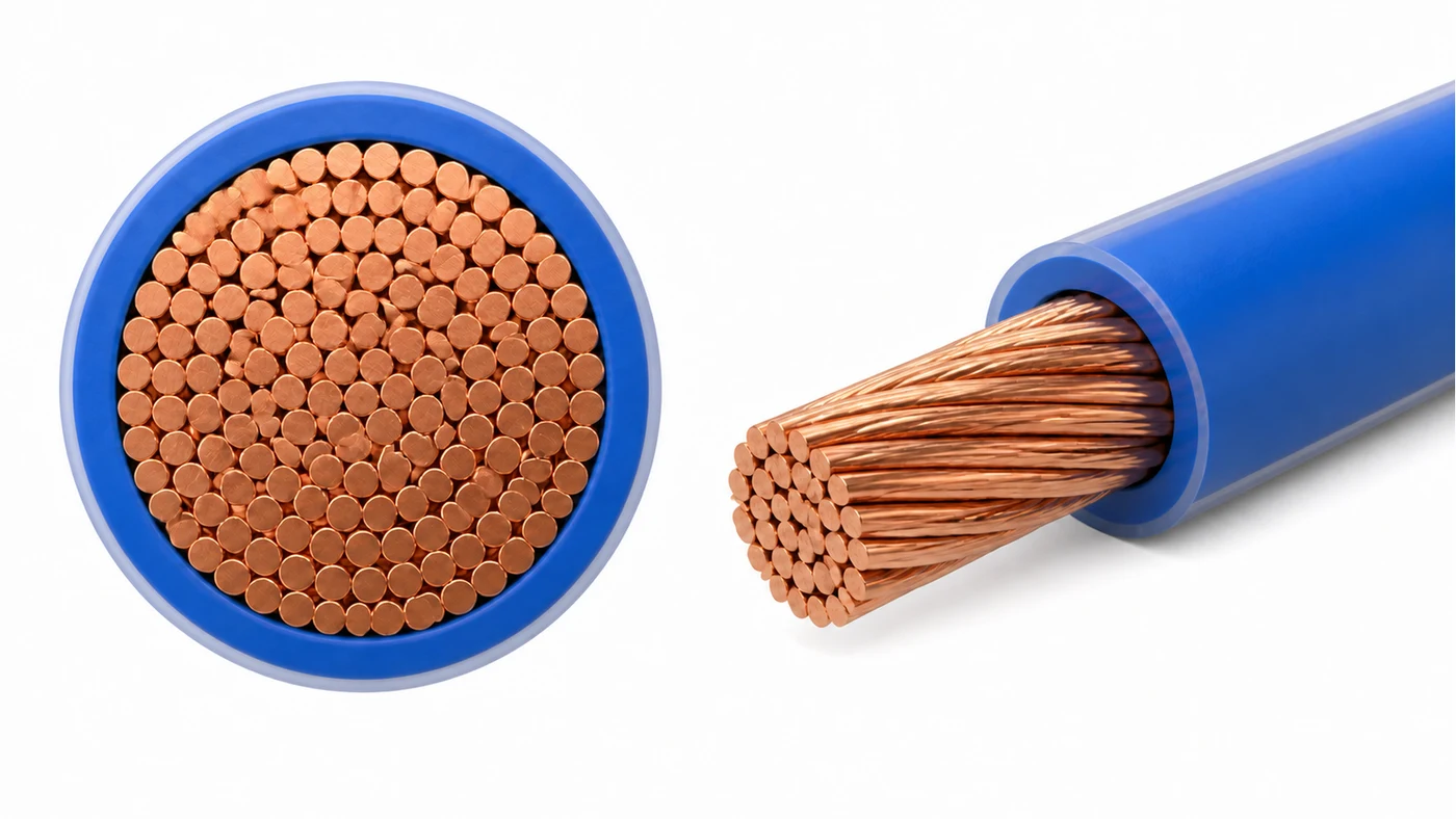
For HONGKAI’s initial review, establish the diameter entering and leaving the relevant extrusion stage before selecting the nylon unit. Apply the same discipline to the PVC stage. With stranded conductors, record the actual conductor outside diameter and construction; a copper cross-sectional area is not a substitute for the outer envelope the extrusion tooling will see.
Use the following layer-boundary worksheet with the customer’s approved wire drawing. The symbols identify dimensions, not recommended sizes.
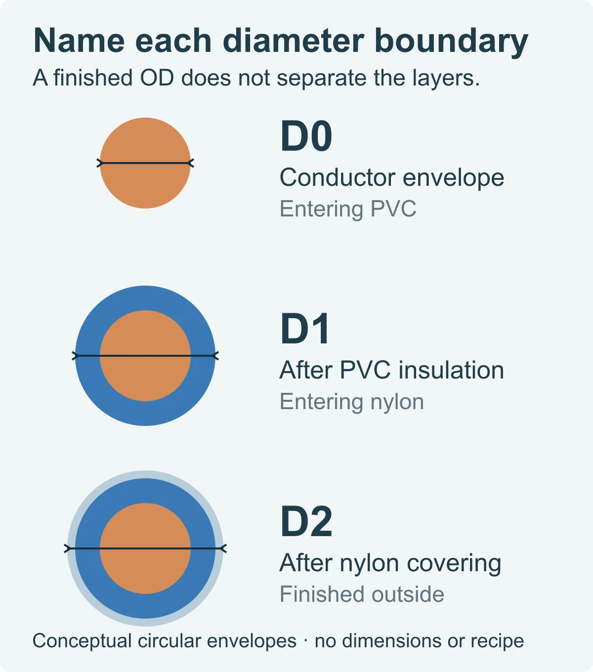
Conceptual layer boundaries: identify the incoming conductor, PVC boundary and nylon boundary separately. No dimensions or product recipe are specified.
| Boundary | Dimension to establish | What it helps the buyer decide |
|---|---|---|
| D0: conductor entering PVC extrusion | Actual conductor outside diameter, construction and allowed variation | Incoming handling and tooling review; whether conductor preparation or stranding is a separate requirement |
| D1: PVC-insulated wire before nylon | Required outside diameter after PVC and the PVC wall requirements | PVC duty and the incoming size for the nylon stage |
| D2: finished nylon-covered wire | Required final outside diameter and the nylon wall requirements | Nylon duty and finished-wire handling |
For an ideal circular, concentric construction, the nominal radial thicknesses are:
- PVC thickness = (D1 − D0) / 2.
- Nylon thickness = (D2 − D1) / 2.
These relationships are a useful consistency check on a proposed drawing. They do not establish minimum thickness around the circumference. A layer can have an acceptable outside diameter while being off-centre, so the technical schedule should state the thickness and eccentricity checks separately.

Conceptual PVC eccentricity comparison: the same finished diameter can conceal different wall distributions. This is not a measured tolerance result.
If the supplied conductor is not well represented by a circular envelope, or if compound fills spaces in a stranded construction, ask for a construction-specific material calculation. Do not quietly treat an ideal annulus as a complete material-consumption model.
Also identify whether the quoted route starts with finished conductors or includes conductor stranding. The stranding machine has its own applicable range. That range does not prove that every downstream crosshead, extrusion stage and handling unit covers the same products.
The result of this first review should be a layer drawing and input schedule that both parties can use. Without that common boundary, one proposal may be sized for a different nylon wall or conductor condition while appearing to quote the same finished wire.
Translate Layer Thickness Into Separate Extrusion Duties
Wall thickness affects the amount of compound required at a given running speed. Compare that demand with the output available for the actual material and operating conditions, rather than choosing a main extruder from its model number alone.
For a first geometric estimate, the cross-sectional area of each circular layer is:
- PVC layer area = π × (D1² − D0²) / 4.
- Nylon layer area = π × (D2² − D1²) / 4.
With all dimensions expressed consistently, layer area multiplied by wire length gives the corresponding ideal layer volume. Multiplying area by linear speed gives volumetric demand. If a mass-output comparison is needed, use the density of the specified compound and convert the units consistently; do not borrow an assumed density from another resin.

Geometric sizing worksheet for ideal circular layers. Keep units consistent and use the actual compound density for a mass comparison; this is not a production trial.
This worksheet is a demand estimate, not an observed production result. It leaves out construction-specific filling and process allowances unless they are explicitly included in the agreed calculation. It also cannot establish whether the actual extrusion arrangement will produce an acceptable surface and wall distribution at the proposed speed.
A thicker layer or a higher required speed changes the output requirement. The diameter under the layer matters as well: the same radial thickness around a larger incoming wire does not require the same material per unit length. That is why the nylon unit cannot be sized from the word “thin” and the PVC unit cannot be sized from conductor area alone.
Ask the supplier to return the calculation basis with the proposal: D0, D1, D2, the intended running rate, compound identities, calculation assumptions and the output basis for each extrusion stage. If the available evidence is a machine maximum rather than a production trial, label it accordingly.
Do not add the output ratings of the PVC, colour-stripe and nylon extruders and call the result whole-line capacity. Those machines serve different material streams. Equally, a capstan’s mechanical speed rating is not evidence that the specified layers can be produced at that speed.
For HONGKAI’s sizing review, the PVC and nylon walls help determine whether a reference main extruder is sufficient or whether a larger unit is required. A choice such as a 70- or 80-class PVC main machine remains conditional on the construction and required compound output. Neither designation establishes a guaranteed product range by itself.
Note: Keep calculated material demand, a machine’s stated capability and demonstrated acceptable-wire output in separate fields. A proposal is easier to compare when these are not presented as the same number.
Decide What an Existing PVC Line Can Reuse
Reuse depends on material suitability and sufficient output for the specified construction, followed by an interface check. A working PVC extrusion arrangement is not evidence that its screw is suitable for the nylon compound or that its existing duty covers the revised wire.
In the HONGKAI approach confirmed for this guide, PVC and nylon use material-appropriate screw arrangements. Do not approve a nylon duty solely because an available PVC extruder has a familiar screw diameter. Establish the intended compound, screw suitability and required output before deciding which equipment remains in service.
This does not mean that every existing line must be replaced. An existing PVC stage may remain a candidate if it supports the required insulation duty, while the nylon stage is matched separately. Where the required wall and running rate demand more output than the proposed unit can provide, the main extruder size or arrangement needs to be reconsidered.
The reuse proposal should identify what stays, what changes and what remains unverified. Include tooling, the incoming diameter to the nylon stage, cooling, pulling and take-up, and the control connections between retained and added equipment. These are review items, not a claim that HONGKAI has already approved the customer’s existing interfaces.
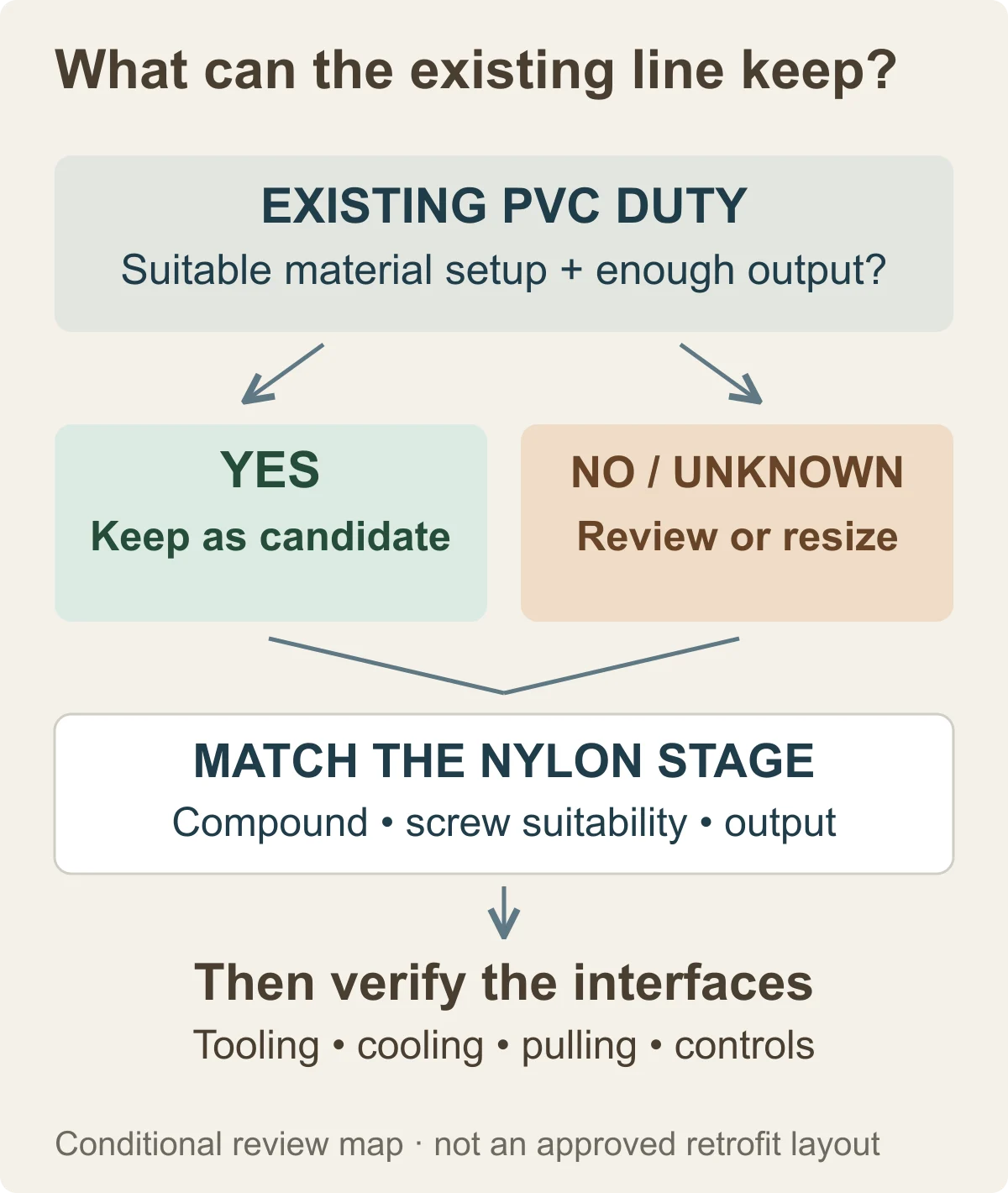
Conditional reuse review: retain a PVC stage only as a candidate until material duty, nylon-stage matching and interfaces have been checked. Not an approved retrofit layout.
What the Φ70 / Φ50 / Φ40 Reference Actually Establishes
O HONGKAI THHN/THWN reference production line separates the PVC main extrusion, colour-stripe and nylon-covering functions. In this particular reference package, the Φ70 PVC main unit, Φ50 colour-stripe unit and Φ40 nylon unit are standard included equipment.
That package is a starting reference, not a universal bill of equipment for every customer. The required walls and output still determine whether the main machine size needs to change. The inclusion of stripe hardware also does not mean every wire specification requires a stripe to be applied.
Keep the discussion focused on functions and verified scope. A buncher range does not become the extrusion line’s range, and a reference layout does not establish compatibility with every existing factory line. The buyer needs an offer tied to the actual incoming conductor and both layer requirements, not just a repeated three-machine label.
If the retained equipment’s relevant details are unknown, the first proposal should identify that limitation. A conditional reuse option is more useful than an unconditional promise that later depends on changing the conductor, reducing speed or altering the required wall.
Verify Both Layers, Then the Finished Wire
Acceptance should distinguish the PVC layer, the nylon layer and the finished product. HONGKAI’s checks described for this guide include thickness, eccentricity, surface condition, spark testing and the specified finished-product tests. Agree the methods and limits for the actual order before the trial.
Record the conductor and material identities with the trial samples. For a surface problem, retain the material-handling and temperature records as well as the observed appearance and measured wall. HONGKAI’s review includes material condition, temperature, surface quality and wall thickness; that scope does not establish a universal fault ranking or one processing recipe for every nylon grade.
BASF’s Ultramid extrusion guidance describes moisture-protective storage and handling for its supplied materials. That supports checking material condition, but it is not a universal drying instruction for the customer’s nylon compound. Use the actual grade supplier’s applicable processing guidance rather than copying film-extrusion settings or another material’s temperature schedule.1
The extruder plasticizes and delivers compound through the tooling; subsequent cooling sets the extruded layer. A visually improved surface alone is not proof that both layers meet their dimensional requirements. Retain the layer measurements and finished-wire test results with the same sample identification.
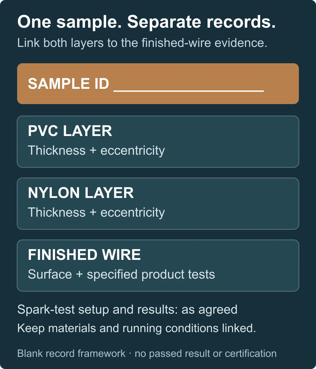
Blank sample-linked acceptance framework. Separate the two layer records from finished-wire evidence; no passed result or product certification is shown.
Evidência a solicitar:
- The approved construction and actual conductor, PVC and nylon material identification used in the trial.
- Separate PVC and nylon thickness and eccentricity records, with the sample preparation and measurement method identified.
- Surface observations linked to the samples and running conditions, rather than an unlabelled close-up photograph.
- The agreed spark-test location, method, settings and result record; an instrument’s voltage range is not the required test setting.
- The finished-product tests specified for the order, with the applicable acceptance criteria and results.
- The demonstrated running conditions and configuration, so that the result can be traced to the equipment and materials actually tested.
Use the cable production line FAT and SAT checklist to organize the trial evidence and unresolved items. For this construction, the important addition is layer-by-layer traceability: a final diameter measurement must not replace the PVC and nylon records, and an isolated machine run must not be described as a complete accepted production route.
UL’s wire and cable application guide distinguishes wire designations and explains product certification marks and the associated evaluation. Purchasing equipment for PVC insulation and nylon covering does not itself certify the finished wire or establish every THHN, THWN or THWN-2 designation. Keep the intended product qualification separate from the machinery supply and trial scope.2
Before approving the configuration, the buyer should therefore have three connected records: the layer construction, the output and reuse assessment, and the agreed acceptance evidence. Together, they show why the offered equipment fits the intended wire and what still has to be demonstrated. A machine list alone cannot answer those questions.
-
BASF Ultramid: Properties and Extrusion Processing Guide, especially “Supply form and storage.” Material-specific guidance, not a THHN wire trial or a universal processing recipe. ↩
-
UL Solutions: Wire and Cable Application Guide, sections on certification marks and wire/cable designations. Equipment supply is not evidence of finished-wire certification. ↩

 English
 हिन्दी
 فارسی