


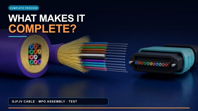
A buyer planning an MPO cable manufacturing process has one central decision. Can the proposed scope release the finished assembly with every channel identified and tested? That decision is broader than choosing a polishing machine.
A complete project links two systems. The GJFJV-type cable route makes and bundles the individual tight-buffered fibers. The MPO workcell then separates, orders and loads them into the ferrule. Both the base cable and the finished assembly need their own release evidence.

Verified-structure 3D reference: this 12-core GJFJV example has a bundled core. The ordered row is formed during ferrule preparation; the signed product drawing controls the saleable construction.
This distinction matters because MPO is a connector interface, not a universal cable construction. The project in this guide uses an indoor multi-core GJFJV-type tight-buffer cable as the reference input. A different launch cable, ferrule family, polarity or optical specification can change the machines, fixtures, test paths and FAT sample.
For a conventional single-fiber connector workflow, see the fiber optic patch-cord production guide. That route is not the equipment list for this MPO workcell.
Scope to Freeze Before Quoting the Complete Line
Freeze the finished assembly, base-cable drawing and release evidence before choosing equipment. An “MPO line” quotation is incomplete without the cable construction, fiber count, connector interface, key orientation, polarity, polish, optical method and traceability unit. These inputs determine the cable-line configuration and the back-end fixtures.
IEC 60794-2-23:2024 addresses indoor multi-fiber cables used in MPO-terminated assemblies. IEC 61754-7-1:2014 and IEC 61754-7-2:2017 cover one-row and two-row MPO interface variants. These publications help define the relevant product and interface layers. The buyer still has to approve the cable drawing, materials, process route and acceptance limits.
| Input to freeze | Buyer decision | Equipment consequence |
|---|---|---|
| Finished product | Named assembly, length and branch format | Cutting, stripping, handling, labeling and test access |
| Cable construction | Fiber count, tight-buffer arrangement, aramid system and jacket | Payoffs, gathering, extrusion tooling, guides and take-up |
| Connector system | Ferrule row, gender, key orientation, housing and polish | Loading and cure holders, polishing fixture and test adapters |
| Fiber and channel map | Fiber category, count, position map and end-to-end polarity | Array fixture, work instruction, polarity tester and data fields |
| Cable acceptance | Dimensions, optical and mechanical requirements, methods and sampling | Online gauges plus separately scoped cable-laboratory equipment |
| Assembly acceptance | End-face, geometry when required, polarity and optical requirements | Inspector, interferometer when required, channel tester and data system |
| Traceability unit | Reel, cut length, connector pair, component lots and traveler identity | Barcode or traveler fields, data export and rework history |
In this guide, the launch product is the signed assembly used to prove the purchased route. A traveler is the linked production record that follows that assembly. Factory acceptance testing (FAT) must connect the launch product, traveler and raw result files.
Decision criterion: This guide uses a Make–Map–Prove–Trace test for quotation completeness. Make the signed base cable. Map every fixture, adapter and software path to the launch product. Prove cable release and finished-assembly release at separate gates. Trace each tested channel back to its source reel, components and process records. If any step lacks named equipment, method or retained evidence, the quoted scope is not yet complete. Approve expansion only for named future products.
GJFJV Cable Making in Two Manufacturing Phases
The verified HONGKAI reference has two manufacturing phases. HK-30 makes the individual tight-buffered fibers. The configured GJFJV phase gathers them, applies the aramid system and extrudes the common jacket. The quotation must state whether the gathering cage is integrated with HK-50 or supplied as a matched unit.
HONGKAI reference route: tight buffering, multi-fiber gathering, aramid application and common-jacket extrusion. The signed project controls the final station arrangement.
Four stages in the GJFJV cable route
-
Tight buffer — Protect each fiber. Pay off the identified fiber, apply the tight buffer, cool it, check the required dimensions and wind the finished buffered fiber.
-
Gather fibers — Create the cable core. Load the identified tight-buffered fibers into the configured gathering system. Form the bundled core shown in the cable drawing.
-
Add the strength system — Apply aramid yarn. Route the specified aramid yarn under controlled tension. Guide the fibers and yarn into the jacket tooling.
-
Jacket and reel — Finish the base cable. Extrude and cool the common jacket. Check the required dimensions and wind a traceable finished reel.
The HONGKAI GJFJV production-line page shows the HK-30 tight-buffer phase and an HK-50 reference line. The visible functions include fiber gathering, aramid payoff, jacket extrusion, cooling, diameter measurement, capstan and take-up. This is configuration evidence, not a universal fiber count, material, speed or layout.
Cable-stage data that should not be deferred to final assembly
Online diameter display is useful, but one screen value is not a complete cable release. The quotation should state which data are displayed, stored or checked offline and which laboratory instruments are included.
| Control point | Record to retain | Separate equipment or decision to scope |
|---|---|---|
| Incoming optical fiber | Reel identity, approved fiber specification and baseline evidence | Incoming optical method and sampling plan |
| Tight-buffer phase | Material lots, fiber identity, process settings, alarms and measured dimensions | Offline dimensional or concentricity method when required |
| Gathering and jacket phase | Buffered-fiber reel identities, aramid and jacket lots, line settings, alarms and diameter evidence | Data logging option and offline cross-section measurement |
| Finished cable reel | Reel length/identity, visual and dimensional release, continuity and agreed optical results | Optical test instruments, reference method and record format |
| Cable qualification | Results required by the approved cable specification | Tensile, crush, bend, temperature or other project-specific laboratory equipment |
Common mistakes: A buyer budgets only the extrusion line because it includes a diameter gauge. Optical and mechanical release tests then remain undefined. A later MPO result cannot replace the base cable’s own acceptance record.
The supplier quotation reviewed for this article contains no cable-making or cable-laboratory equipment. Those items must be added to the complete-project scope rather than inferred from the back-end equipment list.
Complete Back-End Equipment Flow for MPO Assembly
The GJFJV cable brings a bundle of individual tight-buffered fibers into this workcell. The linear row is formed only during connector assembly. A signed channel map—the position-to-position drawing for both connector ends—controls fiber order and polarity.
The supplier quotation identifies equipment for array preparation, adhesive handling, cure, polish, inspection and test. It does not establish the production sequence or process settings. The signed bill of materials, connector instruction and release plan must do that.
The evidence boundary is explicit. The public HONGKAI GJFJV page supports cable-line functions. The supplied MPO catalog and quotation support equipment categories and source geometry. The cited IEC publications support interface and test-method layers. None of these sources establishes a universal recipe, throughput, acceptance limit, certification or customer result. The source-backed 3D images preserve the catalog structures while supplier brands, model text, prices and commercial terms remain excluded.
Four stages from cable end to released assembly
-
Prepare and identify — Expose and order every fiber. Open the cable end without losing fiber identity. Arrange every fiber against the signed channel map.
-
Load and stabilize — Use the qualified adhesive and ferrule route. Prepare the specified adhesive. Load the fibers and ferrule in the validated product-specific sequence.
-
Finish the ferrule — Cure, prepare, polish and inspect. Cure and prepare the ferrule, then run the multi-stage polish. Assemble the hardware at the connector-defined point and inspect the cleaned end face.
-
Verify and release — Confirm geometry, mapping and optics. Measure geometry when required. Verify the channel map and optical results before releasing the linked record package.
For the launch project, each equipment item is mapped to one of three scope labels. Required means required for this launch route, not for every MPO design. Conditional equipment enters only when the signed process calls for it.
Rework equipment stays outside normal production unless an authorized instruction allows its use. This project-specific mapping prevents optional or rework tools from becoming a false universal line. During FAT, run each applicable item with the launch product and keep the device-specific proof named below.
Prepare and identify the fibers
The quoted list starts at array preparation. A complete workcell also needs cable measurement and cutting, jacket removal, aramid preparation and any required component preloading.
Supplier-quoted, source-backed 3D reference: stripping, array handling, adhesive, cure and ultrasonic equipment. Branding and model text are removed.
-
Cable-end preparation. This required operation measures, cuts and opens the cable, prepares the aramid and preloads connector parts. It is absent from the quoted list. Verify the cable identity, dimensions, orientation, preload order and prepared end.
-
MPO thermal fiber stripper. This conditional tool exposes the specified bare-fiber length. Use it only with a compatible fiber and coating. Keep the setting, strip length and damage check from the actual cable.
-
Bare-fiber array arranger. This required device places the separated fibers in one linear order. It follows the channel map; it does not create polarity. Keep a position-by-position check or identified array image.
-
Fiber-array holding clamps. These required clamps keep the verified order stable during loading. Confirm the fiber count, pitch and material match. Keep the fixture ID and post-clamp inspection.
Decision criterion: The cable reel, cut length, fiber identities, end orientation and channel map must share one traveler before adhesive loading.
Prepare adhesive and load the ferrule
-
Centrifugal adhesive degassing unit. This conditional unit prepares a controlled adhesive batch when the material instruction requires it. Link the adhesive name, lot, usable-life status, quantity and cycle to the loaded ferrules.
-
MPO ferrule adhesive-suction unit. The quotation identifies this conditional equipment category; it does not establish a universal ferrule-filling route or acceptance condition. Use it only when the signed connector and material instruction specifies it. Keep the equipment ID, component and material lots, settings and the process verification required by that instruction.
-
Ferrule loading operation. This required step inserts the ordered fibers into the ferrule. The list names no separate powered loader. Keep the ferrule lot, orientation and loaded-array check.
-
Adhesives and process liquids. These are specified materials, not a catalog-defined recipe. Control their identity, lot, shelf life, preparation and working time.
The work instruction must define the adhesive-and-fiber loading sequence. Supplier prices, totals, contact details and commercial terms are not published.
Cure the ferrule and assemble connector hardware
Supplier-quoted, source-backed 3D reference: shell removal, array holding, adhesive scraping and crimping. Branding and model text are removed.
-
MPO curing oven. This required station cures the loaded ferrule in a compatible holder. Keep the adhesive batch, recipe, holder, load, time-temperature evidence and post-cure check. Two quoted ovens do not prove capacity or required redundancy.
-
Adhesive-removal or scraping machine. This conditional machine removes the specified cured material. Define its target, removal boundary and normal or rework status. Keep actual-ferrule before-and-after images and the damage check.
-
Protruding-fiber and cured-adhesive preparation. This required step makes the cured ferrule ready for polish. The connector process must name the permitted method. Keep its revision, ferrule identity and preparation check.
-
Pneumatic connector crimping press. This conditional press assembles compatible hardware or strength-member parts at the connector-defined stage. Prove the jaw and tooling with the actual housing and aramid setup. Keep the tooling ID and assembly inspection.
-
Connector shell-removal tool. This is a rework tool unless the connector instruction states otherwise. Define its permitted use, housing match and rework limit. Repeat the required inspection, polarity and optical checks after reassembly.
-
Ultrasonic process unit. This unit remains conditional because its object, liquid, timing and material compatibility are not yet defined. If selected, keep those inputs, cycle settings and before-and-after inspection.
Polish the selected MPO ferrule
Supplier-quoted, source-backed 3D reference: MPO polishing, full-array inspection and rectangular-ferrule geometry measurement.
-
MPO polishing machine. This required machine runs the multi-stage surface-finishing route. The recipe defines load, time, fixture, cleaning and allowed rework. Keep the machine, program, recipe and rework history.
-
24-position UPC and APC fixtures. Select the fixture that matches each purchased polish. “24-position” is fixture capacity, not fiber count or guaranteed throughput. Keep the fixture ID and result for every loaded position.
-
Pads, films, cloths and liquids. These consumables work as a matched recipe. The list alone does not establish their order, life or compatibility. Keep material identities, lots, usage status and recipe revision.
Clean, inspect and measure the ferrule
-
MPO end-face inspection system. This required gate evaluates the rectangular contact area and every fiber position with a qualified MPO adapter. Keep the image, adapter, method, criteria revision and clean-reinspect-disposition chain. It does not replace geometry or optical testing.
-
MPO ferrule geometry interferometer. This conditional instrument measures specified rectangular-ferrule geometry. The control plan decides full inspection or sampling. Keep the reference state, adapter, raw report, repeatability evidence and product limits.
IEC 61300-3-35:2022 covers visual inspection and classification for contamination, scratches and defects. It includes the complete contact surface of rectangular ferrules and separates visual inspection from other measurements. When geometry evidence is required, IEC 61300-3-30:2026 describes measurement of specified end-face attributes for applicable rectangular multi-fiber ferrules.
Verify channel mapping and optical performance
Supplier-quoted, source-backed 3D reference: end-face, geometry, polarity and multi-channel optical test equipment.
-
MPO polarity or fiber-sequence tester. This required station compares both connector ends with the signed map. It detects an error; it does not define or correct the map. Challenge the actual gender and key orientation, then save every channel result.
-
Multimode MPO optical test system. This required station measures the specified channels of the reference multimode assembly. Confirm the wavelengths, metrics, method, directions and limits. Keep the tester, adapters, reference cords, calibration state, setup and raw values. Scope single-mode or return-loss needs separately.
How to verify: Follow one identified launch assembly through the complete route. Retrieve its cable-reel data, array map, material and cure lots, tooling, rework history, inspection images and required test files. Machine operation alone is not proof that the connected process can release the product.
Release Evidence for Cable and Finished MPO Assemblies
No single pass/fail number covers every failure layer. The base cable needs release evidence before connectorization. The finished assembly then needs channel-specific inspection, mapping and optical results.
| Failure layer | Detecting gate | Release record |
|---|---|---|
| Tight buffer or jacket | Dimensions, process checks and reel inspection | Identified measurements and reel result |
| Cable optical path | Finished-reel optical test by identified fiber | Method, setup and raw fiber results |
| Fiber preparation | Preparation inspection and continuity or downstream result | Prepared-end check and disposition |
| Array order | Array check plus final polarity or sequence test | Signed map and every channel result |
| Adhesive and cure | Material, preparation and approved cure controls plus inspection | Lots, recipe, cycle and post-cure result |
| Polished end face | Full-array visual inspection | Identified image and clean-reinspect-disposition history |
| Ferrule geometry | Interferometer gate when specified | Identified raw report and applicable limits |
| Finished optical path | Channel-level optical test | Equipment, reference setup, raw values and limits |
| Traceability | Traveler and data-file review | One identity linking assembly, lots and results |
These gates answer different questions. A clean end-face image does not prove geometry, polarity or optical performance. An optical pass does not replace the cable-stage record.
IEC 61300-3-4:2023 describes attenuation-measurement methods for optical components. The buyer must still select the method, source conditions, reference arrangement, wavelengths, directions, limits and sampling. If return loss is required, name the equipment and method explicitly; “MPO tester” is not enough.
Pitfalls: Test software uses different channel numbers from the assembly drawing. Rework overwrites the failed result. Master cords or adapters lack identities. Cable and connector records cannot be joined under one assembly ID.
No evidence supports calling one defect universally “most common.” Put a detection gate at every failure layer and preserve the linked records.
FAT Launch Product and Record Package
Use the signed launch product for FAT, not a convenient demonstration sample. A 12-core GJFJV-to-MPO trunk is representative only after its cable drawing, ferrule, key orientation, polarity, polish and optical plan are signed. Demonstrate the purchased cable and back-end route under the same traceability identity.
| FAT gate | Representative run | Record to retain |
|---|---|---|
| Input and cable production | Release materials; make tight buffers and the GJFJV base cable | Lots, input reels, settings, alarms, dimensions and finished-reel identity |
| Cable release | Run the signed dimensional, optical and mechanical plan | Methods, equipment, calibration state, raw results and disposition |
| End and array preparation | Cut and open the cable; identify, strip, arrange and load the fibers | Prepared-end check, channel map, ferrule and adhesive lots |
| Cure and hardware | Complete cure and connector assembly at the defined stage | Recipe, batch, holder, tooling and assembly status |
| Polish and clean | Use the matched machine, fixture and consumables | Recipe revision, fixture, consumable lots and rework history |
| End face and geometry | Inspect every position; measure geometry when specified | Saved images and the identified geometry report when required |
| Mapping and optics | Verify the signed map; test every required channel | Orientation, setup, wavelengths, directions, raw values and limits |
| Handover | Buyer repeats the agreed operation and retrieves its data | Training, manuals, spares, consumables and open-item log |
Evidence to request: The data package must trace a finished channel back to its connector, ferrule, adhesive, prepared cable length, source reel and cable-production record.
Back-end inspection and test equipment are essential parts of the complete-project FAT. One successful run approves only the documented product, tooling and method range. Expansion needs a written compatibility or requalification decision.
Peter He reviewed the project scope used in this article. His input was specific: treat cable-stage results and finished-assembly results as separate acceptance layers. Include the applicable back-end inspection and test route in FAT. These boundaries apply to the signed launch product; they are not a universal MPO recipe.
HONGKAI Complete-Project Responsibility Boundary
HONGKAI insight: HONGKAI can contract the integrated scope. HONGKAI engineers the GJFJV cable-making route and coordinates verified specialist MPO assembly, inspection and test stations. The signed responsibility matrix, launch product and FAT plan—not the catalog or quotation alone—control the final equipment list and delivery scope.
| Scope block | Reference responsibility | What the contract should state |
|---|---|---|
| HK-30 and GJFJV phases | HONGKAI cable-making scope | Product range, configuration, cage arrangement, tooling, FAT and training |
| Cable laboratory | Integrated or buyer-supplied by agreement | Instruments, methods, calibration, utilities and sampling |
| MPO assembly equipment | Specialist equipment integrated into the project | Source, fixtures, work instructions, consumables, FAT and training |
| MPO inspection and test | Specialist equipment integrated into the project | Compatibility, adapters, software, data fields and calibration |
| Site, documents and samples | Assigned in the contract | Utilities, drawings, components, limits, samples and approvals |
| Installation and after-sales | Named by equipment group | Lead party, specialist participation, escalation and spares |
What to ask: Require one responsibility matrix rather than separate supplier promises. Public equipment images are presentation references; the signed list, drawings and FAT machines control delivery.
Checklist:
-
☐ The cable line and laboratory plan match the signed GJFJV construction
-
☐ Every back-end machine and fixture maps to the launch connector process
-
☐ Array order and final polarity use the same signed channel map
-
☐ Visual, geometry and optical gates have separate acceptance evidence
-
☐ Cable and assembly records share one traceability chain
-
☐ Responsibilities are named, and FAT retains raw data instead of pass labels
A complete line is not complete just because every machine is present. It becomes complete when one approved product moves from verified cable inputs to release with linked process and test evidence.
