










For a cable factory making several colors or compounds, a changeover affects more than the material in the hopper. Production managers need to know when the old product ends, which cable length belongs to the transition, and what makes the first new reel acceptable.
A visible color change is one observation, not the complete acceptance decision. Define the old and new products, use the authorized transition procedure, and identify the first new output supported by the required checks. Compare changeovers on that same basis.
This is a buyer’s guide to specifying and evaluating a changeover. It is not a purge recipe or an instruction to open, clean or restart operating machinery.
Separate a Color Change from a Material Change
Consider an illustrative enquiry: a factory wants to change a jacket from blue to grey while retaining an identified PVC compound system and cable drawing. That is a different duty from changing the material system from PVC to PE. Neither description alone proves that the proposed machine and transition method are suitable.
For a color-only change, establish the old and new colorant identities, dosing arrangements and appearance requirements. For a material change, establish both exact compound grades and their applicable processing and transition instructions. Also state whether tools, dimensions or layers change at the same time.
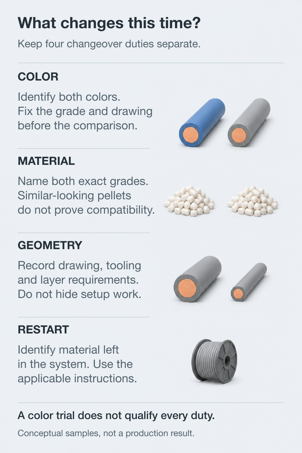
Figure 1. Conceptual sample comparison: color, exact compound grade, geometry and restart are separate changeover duties. The samples do not identify polymer grades or prove interchangeability.
| Change being requested | Information to fix before comparison | What must not be assumed |
|---|---|---|
| Same identified compound system, different color | Both color systems, dosing arrangement and accepted color reference | A clean-looking new color proves every product requirement |
| Different compound grade or material system | Exact outgoing/incoming grades and an approved transition method | A familiar polymer name makes the grades interchangeable |
| New dimensions or tooling | Both drawings, tool identities and layer requirements | A color-change trial also qualifies the new geometry |
| Restart after a stop | Material left in the system and the applicable restart instructions | A running color change represents the same duty |
Davis-Standard discusses resin behavior and color sequence as factors in planning product changes. Its illustrated color example uses PET; that is not a procedure for cable-grade PVC, PE or LSZH compounds.1 Use the source to frame a material-specific review, not to prescribe one sequence for every cable factory.
Where the change includes tooling or layer dimensions, review the separate crosshead, tooling and wall-verification requirements. Keep that setup duty visible in the trial instead of attributing all elapsed time to purging.
Locate What Remains in the Material Path
Changing the hopper is a feeding event. It does not document the condition of the complete installed material path.
Map the actual equipment: loading and dosing, the main extruder, connected adapters or distributors, the crosshead and any auxiliary color or layer extruders. Identify only components that are present. If a stripe or skin uses a separate path, include that path in the scope rather than inspecting only the main feed.
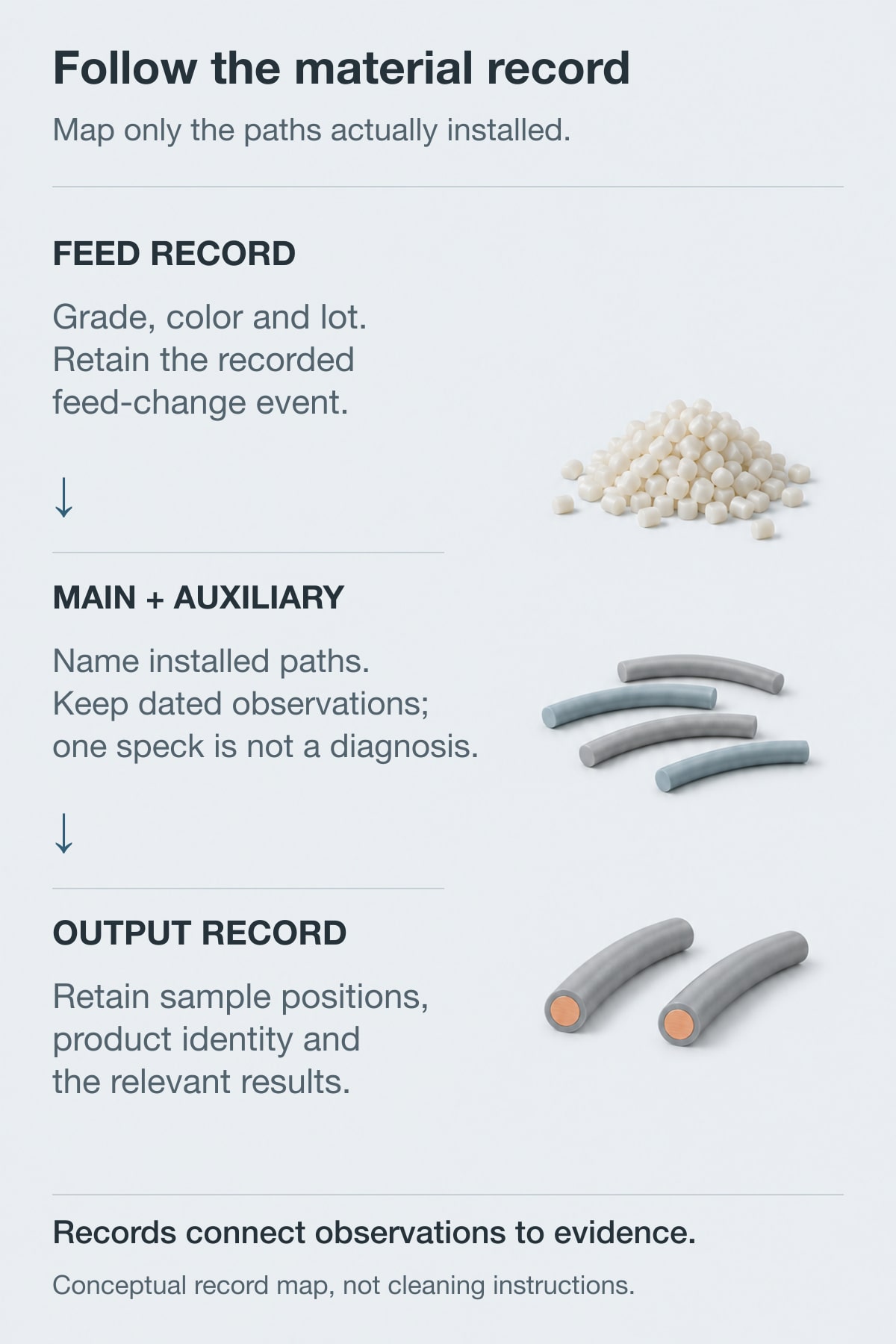
Figure 2. Conceptual record map, not a machine layout or cleaning procedure. The middle samples are solid polymer without conductors; record only the main and auxiliary paths actually installed.
Davis-Standard identifies stagnant material, unsuitable operating conditions, damaged flow surfaces and incoming contamination among possible contributors to off-spec extrusion.1 These are possibilities to investigate, not a diagnosis from one black speck or photograph.
A production manager can organize the investigation with a simple observation record:
| Observation after the change | Useful evidence to retain | Question for the authorized investigation |
|---|---|---|
| The previous color appears again | Sample position, material identities and recorded feed/change events | Which installed paths and feeding records still need review? |
| Black specks or another surface defect remain | Samples before/during/after the change and their material lots | Is the condition associated with incoming material, the process or a component requiring inspection? |
| Color looks consistent but dimensions are not acceptable | The same-position dimensional results, tooling identity and process record | Is the remaining problem a setup or stability issue rather than simply color clearance? |
| One sample looks acceptable, but a later sample does not | Both positions and any intervention between them | What interval can the evidence actually support? |
The table organizes questions; it does not identify a faulty part or authorize cleaning work. Do not change several settings and then describe the improved sample as proof of a single cause.
Note: Purging, intrusive cleaning, tool changes and restart work require trained, authorized personnel following the applicable equipment and material instructions. Davis-Standard states this manual-based boundary; its published shutdown/restart procedure is a blown-film example, not a universal cable-line recipe.2 No cleaning compound, temperature, screw speed, pressure limit or dismantling sequence is prescribed here.
For the buyer, the required output is a defined procedure and responsibility, not an improvised method during commissioning. Record who approves the transition for the actual material pair and who decides whether an unresolved observation needs further investigation.
Define First Good Cable Before Counting Changeover Loss
Agree what the first accepted new output must demonstrate before timing the trial. The inspection plan may include appearance, surface condition, dimensions, wall distribution and the tests required for the identified cable. Select the actual methods and limits from the product requirements; this guide does not prescribe an identical test set for every cable.
A photograph of the new color, a stable diameter display and a finished-cable test report answer different questions. Their records should identify the same product and relevant production positions before they are used together.
A Hypothetical Counter Example
Assume a continuous length counter is retained without reset. For this example, the factory has chosen the last accepted old-product boundary as the start of an identifiable transition interval.
| Event in this hypothetical record | Counter position | Meaning |
|---|---|---|
| Last accepted old-product boundary | 12,500 m | Start of the interval to keep identifiable |
| New feed selected | 12,620 m | Feed changed; clearance has not been demonstrated |
| New color first judged visually consistent | 12,860 m | Appearance observation only |
| New-output boundary supported by the agreed checks | 13,220 m | Proposed end of the interval, subject to those results |
The identified interval is 13,220 − 12,500 = 720 m. This is an arithmetic illustration, not a measured factory result or a promised loss figure.

Figure 3. Hypothetical continuous-counter example: 13,220 − 12,500 = 720 m is the identifiable transition interval, not a measured result or automatic scrap quantity. Later report approval must remain linked to the original sample position.
It is also not automatically 720 m of scrap. Keep the material identifiable and record its actual disposition under the factory’s quality procedure. Any decision to release part of the interval needs the applicable product identity and evidence; subtraction alone cannot make that decision.
If an offline result is approved later, retain the specimen’s original production position. Do not confuse the time of the quality decision with the time or counter position at which the specimen was made. Likewise, a first accepted sample does not automatically qualify every later meter.
Keep four quantities separate when comparing proposals:
- Transition length: the defined cable interval.
- Loose purge material: material collected outside the cable stream.
- Final disposition: the quantities released, held, reworked or rejected.
- Elapsed time: time between explicitly named events, including any agreed stops or setup work.
Do not add kilograms of loose purge to meters of cable, or count the same rejected material twice when converting units. State the measurement basis for each stream.
Keep this ledger separate from the extruder-output and whole-line capacity calculation. A running-output rating and the accepted cable length over a production period are different planning measures.
Ask What an Automatic Color-Change System Actually Changes
Automatic color change is not a complete specification. Ask which material path, layer and control function change, and which parts of the product remain unchanged.
A dosing change, a skin or stripe change, and a change of the main insulation or jacket compound should remain separately described duties in the quotation. A demonstration of one should not silently qualify the others.
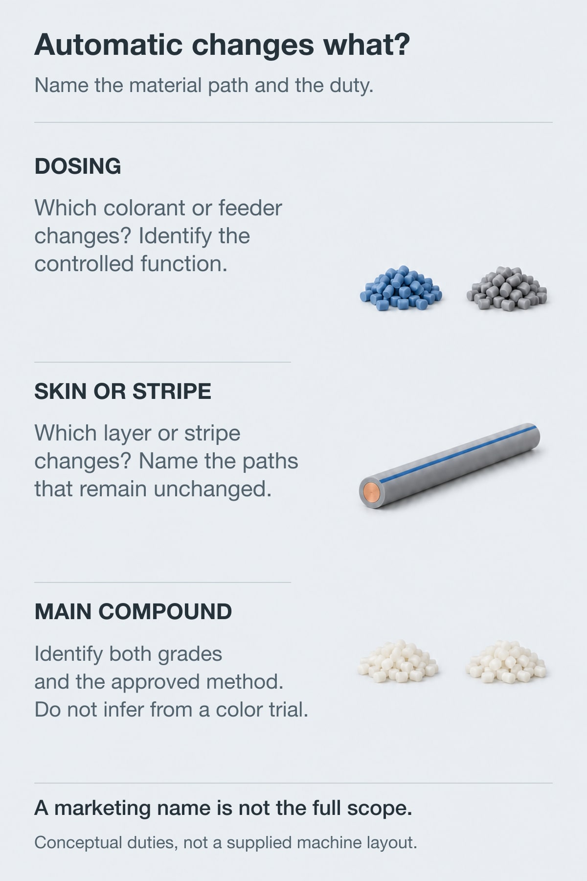
Figure 4. Conceptual duty comparison, not a switching-valve or layer-flow diagram. Dosing, skin/stripe and main-compound changes need separate scope descriptions; the figure does not depict Maillefer X-flow or a supplied HONGKAI configuration.
Maillefer’s Single Valve X-flow System provides a specific documented example: a main extruder, two auxiliary extruders, a switching valve and a triple-layer crosshead for skin or striping color changes. The auxiliary streams exchange their layer roles.3 This named arrangement does not establish compatibility or supplied scope for a different machine.
For an offered system, put the product cross-section next to its flow-path description. Identify the layer that changes, the paths that retain the existing material, and the locations of the relevant measurements. The explanation should still make sense when the marketing name is removed.
Then inspect the claimed performance boundary. Does a stated time cover a control action, arrival of the new color or the first output accepted against the agreed inspection plan? Does the corresponding length include tool setting, reel handling or a stop? Keep these definitions visible before comparing figures.
No vendor-specific changeover time, saving or retrofit capability is assumed here. The relevant result is the one demonstrated for the proposed equipment, material identities and cable construction.
Demonstrate the Transitions the Factory Will Actually Run
Choose trial transitions from the intended product mix. A useful planning matrix lists outgoing products against incoming products and marks each pairing as demonstrated, pending review or outside the accepted scope.
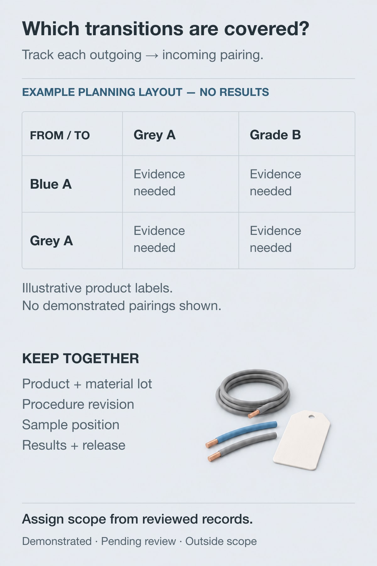
Figure 5. Illustrative planning matrix only: no pairing is shown as demonstrated. Replace the generic product labels with actual identities and assign demonstrated, pending review or outside-scope status only from reviewed records.
The matrix makes gaps visible. A demonstration from one color to another does not fill every color pairing. A color-only trial does not fill the cells for a compound change, different layer arrangement or restart. Agree the representative transitions and number of demonstrations for the project rather than imposing a universal test count.
For each selected transition, keep the two product identities, material lots, procedure revision, equipment/tooling arrangement and event positions together. Attach the relevant results and disposition. Retain interrupted or unsuccessful trials as well as the favorable one.
How to verify: Select a claimed first-good position and follow it to the retained specimen, applicable results and release decision. Then follow the last-old boundary and separately collected purge material through the same record. Confirm that every reported time, length and mass uses the agreed definitions without overlapping categories.
Agree who owns machine operation, procedure approval, product testing and release. If part of the verification is performed by the buyer or a separate laboratory, show the outstanding work instead of treating it as supplied with the machine.
The practical handover is a reviewed transition matrix and a reproducible record for the next order: which product pairing is covered, which instructions apply, what material remains identifiable, and what evidence supports release. That is the basis for judging whether a proposed changeover arrangement fits the factory’s production schedule.
-
Davis-Standard, Essential Feedscrew and Barrel Maintenance III, Purging – Part 1 of 3. Supports the limited scheduling and potential-contamination discussion. Its PET example and operating suggestions are not adopted as cable-compound instructions. ↩ ↩
-
Davis-Standard, Effective Shutdown and Restart Procedures – Purging 2 of 3. Supports the trained-personnel/manual boundary and identifies the published procedure’s blown-film context. No operating recipe is transferred. ↩
-
Maillefer, Single Valve X-flow System 12/16. A named example of skin/stripe switching architecture, not a HONGKAI configuration, universal retrofit or verified production result. ↩

 English
 हिन्दी
 فارسی