












A fiber optic cable factory owner, production manager or technical buyer planning an ADSS cable production line must connect the approved cable design to every manufacturing stage. The practical question is not whether a supplier offers an “ADSS line,” but whether the proposed route can control each component, interface and acceptance result required by the target cable.
A defensible ADSS production route begins with the finished cable specification and works backward through outer sheathing, aramid reinforcement, cable-core stranding, loose-tube formation and fiber preparation. Existing equipment can remain in scope only when its material handling, package, tension, process window and test evidence match the approved ADSS construction.
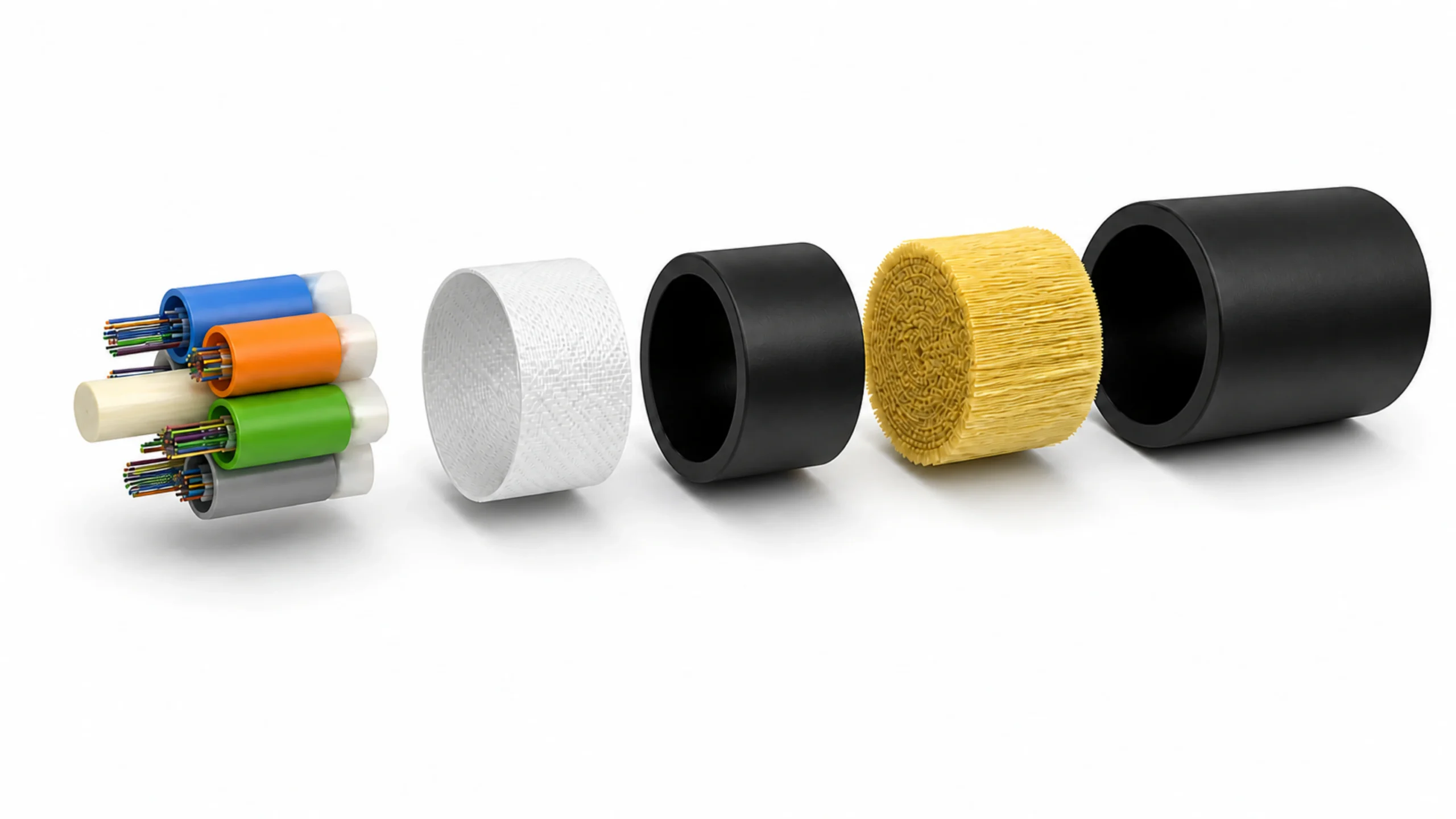
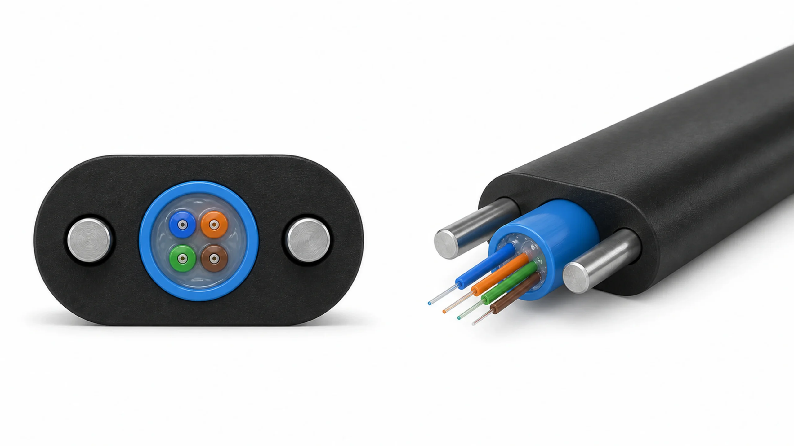
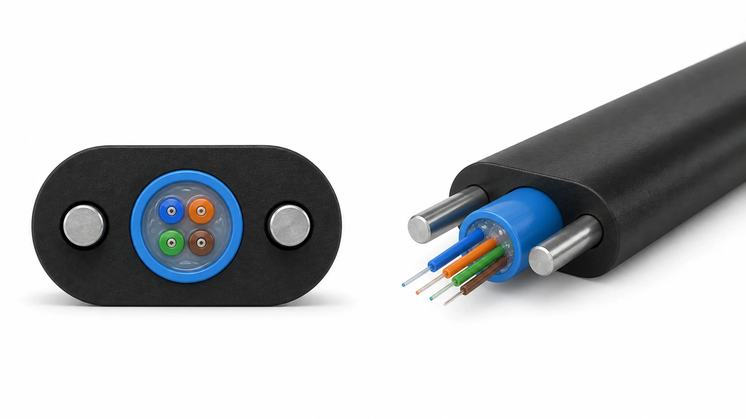
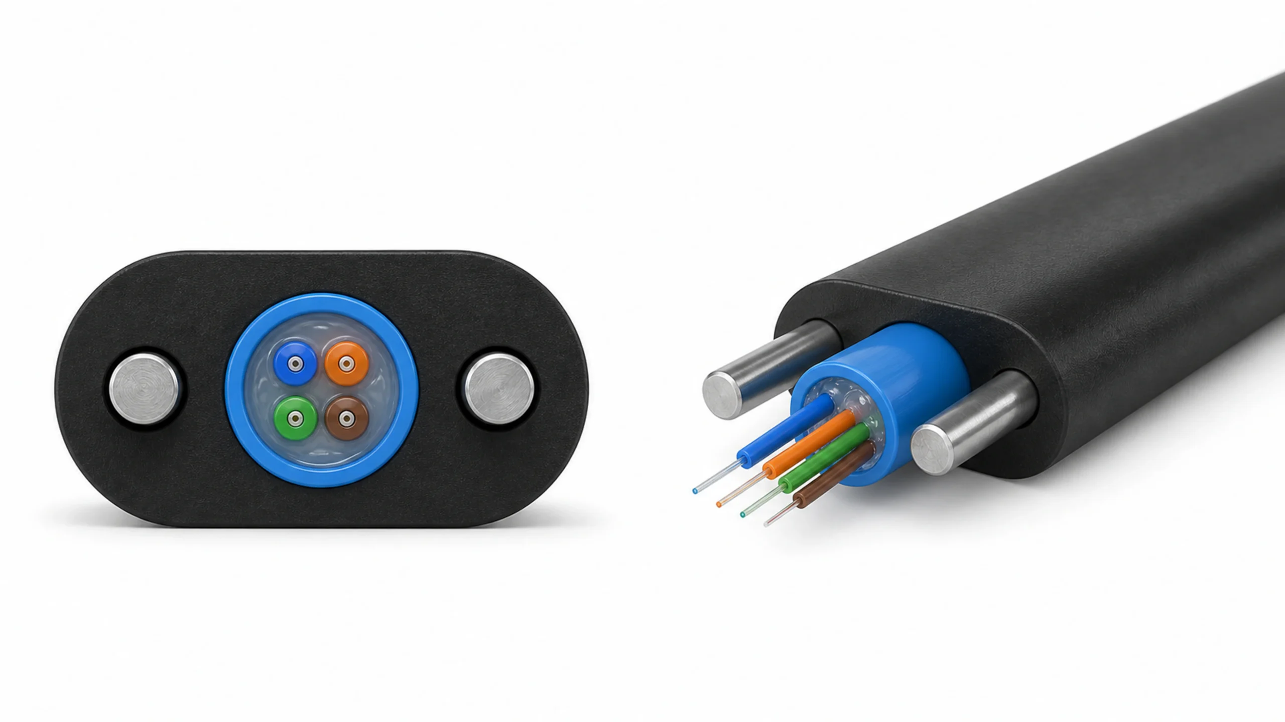
Verified reference illustration of a stranded loose-tube ADSS construction. Final layer count, dimensions, materials and performance requirements must follow the approved cable drawing.
This guide replaces HONGKAI’s older process article at the same URL. It separates product requirements from machine claims, treats the current HONGKAI ADSS cable production line as a reference route, and keeps machine quantities and operating values project-specific.
What Must Be Defined Before Choosing an ADSS Production Route?
Start with the target cable, installation environment and acceptance specification. Fiber count or finished diameter alone cannot determine the loose-tube design, cable-core arrangement, aramid requirement, sheath compound, production equipment or FAT program.
ADSS means all-dielectric self-supporting cable. The tensile reinforcement is non-metallic, and the finished design must support itself under the specified aerial installation and operating loads. The current IEC 60794-4-20:2018 scope covers ADSS construction as well as mechanical, electrical, optical, environmental, installation and acceptance requirements. The standard does not certify a machine or define one universal factory configuration.
The buyer’s first engineering package should include:
- the approved cable cross-section and material schedule;
- fiber type, fiber count, color sequence and supply reel format;
- loose-tube count, tube dimensions, fibers per tube and filler arrangement;
- central dielectric member, water-blocking and binder construction;
- inner-sheath requirement, aramid layer design, ripcord and outer-sheath construction;
- the applicable product standard, project specification and installation environment;
- the intended span, route type and application scenario, together with the customer’s product-specific dimensional and performance limits;
- required mechanical, optical, environmental and electrical tests;
- input and output package drawings for every production stage.
An aerial cable used near power lines and a self-supporting cable used on a telecommunication pole route may fall under different performance and sheath-design requirements. For example, IEC 60794-3-20:2016 covers self-supporting aerial telecommunication cables but explicitly excludes ADSS constructions on power lines that require special tracking- and erosion-resistant sheath materials. The project specification must identify the applicable route rather than using “aerial cable” as a complete design input.
Common mistakes: A buyer sends only fiber count, span or finished diameter and asks for a complete machine list. Another mistake is to copy a previous ADSS bill of materials without confirming line voltage, environmental exposure, loading, cable diameter, tensile design and required test program.
Decision criterion: Treat “ADSS + fiber count + span” as an incomplete input set. Request the detailed product construction and specification before validating a production route, because those inputs define both the machine configuration and the acceptance basis for the trial. A machine’s theoretical capability does not by itself prove that the customer’s target cable has been validated.
How Does the Cable Structure Map to the Production Stages?
Map each material layer to the stage that creates or integrates it, then define the handoff between stages. A reference stranded loose-tube ADSS route normally includes fiber preparation, loose-tube extrusion, SZ core stranding, aramid reinforcement and outer sheathing, followed by product testing and packing.
| Cable element or output | Manufacturing responsibility | Reference HONGKAI module | Buyer evidence before selection |
|---|---|---|---|
| Colored optical fibers | Prepare identification and controlled supply reels when pre-colored fiber is not used | HK-235 coloring and rewinding | Fiber specification, color sequence, reel format and qualification record |
| Filled loose tubes | Feed fibers, meter filling compound, extrude and cool the tube, control geometry and take up the qualified tube | HK-50 loose-tube production line | Tube material, fibers per tube, tube drawing, excess-length method and test plan |
| Stranded cable core | Pay off the central FRP and loose tubes, apply SZ stranding, bind and add specified water-blocking elements | HK-SZ / HK-800-12 reference route | Element count, dimensions, lay plan, reversal requirements, tension window and core test record |
| Aramid-reinforced core | Apply the specified dielectric tensile reinforcement with controlled distribution and tension | Project-specific aramid reinforcement system | Yarn type, package, layer design, quantity, tension method and coverage evidence |
| Finished outer sheath | Pay off the approved core, integrate reinforcement/ripcord interfaces, extrude, cool, measure, pull and take up | HK-90 ADSS sheathing route | Compound, sheath construction, markings, geometry, spark/online checks and final reel |
| Released ADSS cable | Test the agreed optical, dimensional, mechanical and environmental requirements | Buyer laboratory, qualified third party or agreed test scope | Test method, sample, instrument, limit, witness party and retained report |
This matrix is a process map, not a universal bill of equipment. A factory that buys qualified pre-colored fiber may not need a coloring line. A factory with a verified loose-tube or SZ line may reuse it if the approved materials, packages, process limits and quality evidence fit the new ADSS range.
- Process names alone do not prove equipment reuse. An existing optical-cable plant may already have coloring, loose-tube extrusion, SZ stranding or sheathing equipment, but the decision must still be made against the target product and required operating tier. Low-, medium- and higher-throughput configurations can differ in control scope and line capability even when the process names are the same.
-
::flow
01 · DEFINE|Approve the cable
Freeze the construction, materials, applicable standard, launch products and acceptance requirements.
02 · MAP|Assign each layer
Identify which stage forms or integrates every fiber, tube, strength member, water-blocking element, yarn, ripcord and sheath.
03 · MATCH|Audit equipment
Compare existing and proposed machines against the required packages, tensions, geometry, controls and factory interfaces.
04 · PROVE|Run acceptance
- Use traceable materials and representative cable to verify the agreed process window and finished-product evidence.
-
::
Decision criterion: Do not purchase a “complete ADSS line” until every row in the structure-to-process matrix has an assigned machine, responsible party, input specification, output record and acceptance method.
Which Process Interfaces Are Most Likely to Break the Route?
The highest-risk points are usually the handoffs between stages, not the presence of the headline machines. A qualified loose tube can still be damaged during payoff or SZ stranding; a stable cable core can still fail if aramid distribution, sheath extrusion or take-up handling is not coordinated.
Fiber preparation to loose-tube extrusion
Confirm whether the plant will use pre-colored fiber or color and rewind it in-house. The handoff must preserve fiber identification, coating condition, reel build and payoff behavior. The loose-tube line then needs the correct fiber reel interface, filling system, tube material preparation, extrusion tooling, cooling path, online geometry check and take-up package.
The tube drawing should define more than nominal outside diameter. It should state wall construction, fiber count, fiber excess-length requirement, filling condition and test method. A stable-looking tube is not sufficient if the optical result changes after cabling, temperature conditioning or mechanical loading.
Loose tubes to SZ cable-core stranding
The SZ stage must receive loose tubes and the central FRP in compatible packages and controlled condition. Confirm element diameters, counts, fillers, central-member interface, lay or reversal program, binder and water-blocking materials, tension method, capstan and output reel. These variables are connected; they should not be approved as separate catalog options.
Check the cable core after stranding for geometry, tube condition, binding stability and the agreed optical evidence. The line trial should also show starts, stops, reversal behavior, acceleration and the reel build required by the next stage. A short no-load rotation test cannot prove the cable-core handoff.
Cable core to aramid reinforcement and sheathing
The final-stage proposal must show where the cable core is paid off, where aramid is applied, how the yarn packages are loaded and controlled, where ripcords or other specified elements enter, and how the reinforced core reaches the crosshead. The downstream extruder, cooling path, diameter measurement, traction and take-up must follow the same coordinated line-speed reference.
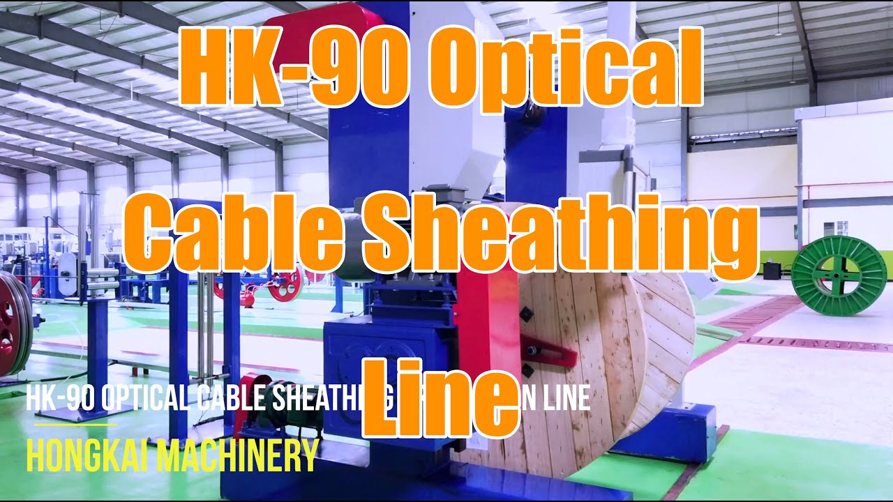
Real HONGKAI HK-90 optical cable sheathing-stage reference. The complete aramid arrangement, line interfaces, dimensions and operating range require project confirmation.
Note: The product page groups aramid reinforcement and final sheathing into the last reference stage. The signed proposal must still state whether the reinforcement system is a separate machine, an inline module or another verified arrangement and how its controls interlock with the sheathing line.
What Must the Aramid Reinforcement Process Control?
Aramid is a structural input, not decorative yarn added before the jacket. The process must distribute the specified reinforcement around the cable core without unacceptable local stress, gaps, overlap, twist, yarn damage or unstable handoff into the sheath crosshead.
The required yarn type, linear density, treatment, package, number of ends and layer design come from the approved cable construction. Machine selection must then address package dimensions, loading, individual or grouped tension control, yarn path, guiding, break detection, stranding direction or application pattern, changeover and line synchronization. Do not infer these values from cable diameter alone.
Derive the required number of aramid ends from the approved cable construction; a structure needing more reinforcement may require more active yarn packages. For ADSS projects with multiple yarn ends, evaluate an active payoff with tension control rather than assuming that passive line pull will be adequate. A cage-type arrangement is a HONGKAI reference configuration, but its head count, layer pattern and suitability must be confirmed for the approved cable.
The aramid system and sheathing process must be reviewed together. A mismatch can disturb the reinforced-core diameter, yarn distribution, crosshead entry, jacket concentricity, surface appearance or take-up behavior. The FAT should therefore capture evidence before, during and after sheathing rather than hiding the reinforcement layer inside the finished sample.
Some approved constructions include an inner and outer sheath, while others do not. The application scenario—including whether the cable is intended for a backbone route or another installation environment—must therefore be supplied before HONGKAI freezes the sheath and aramid arrangement. This project-specific review must not be replaced by the assumption that every ADSS cable uses the same final-stage configuration.
Evidence to request:
- approved yarn identification and package details;
- a thread-up diagram and recorded tension-control method;
- verification of the active yarn ends and layer arrangement;
- images or retained samples showing distribution before sheathing;
- recorded line settings for the representative product;
- finished-cable geometry and optical results linked to the same run;
- the agreed mechanical tests or qualified external reports for the final design.
Red flags: The proposal states only a head count, treats all yarn packages as interchangeable or claims one tension value for every ADSS design. Another warning is an FAT plan that inspects only the outer jacket and never records the reinforced core before it enters the crosshead.
Which Quality Evidence Belongs at Each Stage?
Separate process checks from finished-cable qualification. Factory acceptance can prove machine assembly, interfaces, repeatable settings and representative production evidence, but the finished ADSS design may also require mechanical, optical, environmental and electrical tests that are not practical on the production floor.
| Stage | In-process evidence | Output evidence | Boundary to record |
|---|---|---|---|
| Fiber preparation | Reel identity, color sequence, winding condition and payoff behavior | Color-adhesion/no-color-loss evidence and qualified prepared fiber reel | Whether fiber is buyer-supplied, pre-colored or processed in-house |
| Loose-tube extrusion | Material lot, fiber feed, filling, temperature/pressure recipe, cooling and online geometry | Controlled fiber excess length, stable tube outside diameter, optical evidence and reel build | Which tests are line checks and which require a lab method |
| SZ stranding | Element identity, payoff tension method, lay/reversal settings, binder and water-blocking application | Normal cable-core formation, tube condition, binding stability, optical result and output reel | Which product and operating condition represent acceptance |
| Aramid application | Yarn identity, active ends, package condition, tension method, path and distribution | Reinforced-core diameter, coverage evidence and retained sample | Layer design and pass limits from the approved cable specification |
| Outer sheathing | Compound identity, crosshead/tooling, extrusion/cooling settings, aramid application, online diameter and line synchronization | Sheath surface, outside diameter, eccentricity/deviation, marking, length, reel build and agreed online tests | Compound and electrical-environment requirements are project-specific |
| Finished cable | Traceability from materials and recipes to sample | Optical, dimensional, mechanical, environmental and applicable electrical reports | Test location, witness, sample length, method, limit and responsibility |
IEC 60794-4-20:2018 includes ADSS acceptance and test requirements at the product level. ITU-T L.102 (11/2025) defines ADSS as a self-supporting cable whose tensile element is non-metallic reinforcement under or within the plastic sheath and discusses aerial-cable construction and performance considerations. Newer test-method publications can also apply to specific phenomena: IEC 60794-1-119:2025 defines an aeolian-vibration test method for aerial optical cables including ADSS.
These sources help define what the cable must prove. They do not establish that every test belongs inside a machinery FAT or that HONGKAI supplies every laboratory. The RFQ should assign each required result to machine FAT, buyer laboratory, independent laboratory, type-test evidence or another agreed verification route.
How to verify: Select the FAT cable from the customer’s approved product specification, then keep stage-linked evidence: color adhesion after coloring; fiber excess length, optical result and outside-diameter stability after loose-tube extrusion; normal cable-core formation after SZ stranding; and aramid application, sheath surface, diameter and eccentricity/deviation at the final stage. Exact limits remain those of the agreed product specification. If the complete line does not produce a conforming cable, start with the failed finished-cable characteristic and trace it backward—for example, color loss, poor excess-length control or excessive loose-tube diameter variation—to the responsible upstream process.
How Should Existing Equipment Be Audited Before Buying a Complete Line?
Audit the plant stage by stage and keep only equipment that can prove the required input, process and output window. Reusing a machine because its nominal diameter or speed appears sufficient can leave hidden gaps in yarn handling, package interfaces, controls, test capability or downstream compatibility.
For each existing line, collect the nameplate and configuration, general arrangement, payoff/take-up drawings, tooling, control architecture, material limitations, maintenance condition and recent qualified product records. Then compare those records with the launch ADSS matrix. Mark each stage as reusable, reusable with modification, new equipment required or external responsibility.
The HONGKAI loose-tube production line guide can help define the tube-stage inputs, while the fiber optic cable production-line installation guide explains project interfaces that should be frozen before commissioning. Use these pages as planning references, not as substitute technical agreements.
Checklist:
- ☐ Approved ADSS product matrix and applicable standards
- ☐ Existing-machine configuration and condition records
- ☐ Input and output reel drawings for every stage
- ☐ Material grades, package formats and storage conditions
- ☐ Tooling, crosshead, dies, guides and change parts identified
- ☐ Line-control, synchronization and data-recording interfaces
- ☐ Utilities, floor layout, lifting, guarding and operator access
- ☐ In-process and final test responsibilities assigned
- ☐ Representative FAT products, pass limits and retained records
- ☐ Modification, installation, training and handover boundaries
Common mistakes: A factory counts machines instead of verifying stage interfaces, or assumes the existing laboratory can perform every project-specific ADSS qualification test. A gap register is more useful than an optimistic “complete line” label.
What Should the RFQ and FAT Package Contain?
The RFQ should make the supplier map the cable construction to the proposed route, and the FAT should prove the agreed representative operating conditions with traceable records. Commercial comparison should begin only after the technical scope and evidence matrix are aligned.
Send the supplier a controlled input pack containing the cable drawing, material schedule, product matrix, standards, stage capacities required by the production plan, package drawings, factory utilities, existing-equipment interfaces and acceptance matrix. Ask for a returned line-by-line responsibility schedule that identifies every supplied machine, optional module, buyer item, utility, test instrument and excluded scope.
For FAT, select products that exercise the important boundaries of the proposed route. The chosen sample should be stated by construction, materials, package, lay/reversal program, aramid layer, sheath and test method—not merely “one ADSS cable.” Record material lots, setup, recipes, line condition, sample length, measuring instruments, pass limits, deviations and retained samples or files.
The HONGKAI ADSS solution page uses HK-235 fiber preparation, HK-50 loose-tube extrusion, HK-SZ core stranding and HK-90 reinforcement/sheathing as a reference route. HONGKAI can use the buyer’s approved product matrix to review which modules are new, which can be integrated with existing equipment and which tests remain the buyer’s or a laboratory’s responsibility.
Note: No machine list, head count, speed, output or test package is universal for ADSS cable. Final values and responsibilities belong in the mutually approved technical proposal and FAT plan.

 English
  हिन्दी
  فارسی
فارسی