


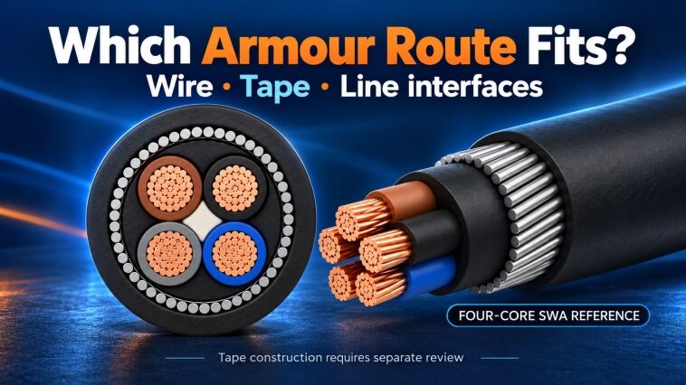
A power-cable factory adding armouring must buy a process that fits the approved cable construction and the equipment on either side of it. The decision is not complete when a quotation contains an armouring machine: the incoming bedded core, armour feed, outgoing cable and drum-handling arrangements must fit together.
Define the armour layer before choosing the machine. Keep wire armour and tape armour as separate equipment duties, check the bedding and sheathing interfaces, and require trial evidence tied to the construction actually ordered.
This guide concerns machinery scope and production planning. It is not a cable-design specification, an installation instruction or a declaration that a particular armour material is suitable for the buyer’s electrical application.
Freeze the Armour Definition Before Comparing Equipment
An enquiry headed armoured cable is not yet an equipment input. Ask for the approved construction drawing and identify the metallic layer separately from the conductor, insulated-core assembly, bedding and outer sheath. Use the drawing revision as the common reference for every supplier’s offer.
Steel wire armour, often abbreviated SWA, and steel tape armour, often abbreviated STA, require different material feeds and application arrangements. Do not accept a shared machine-category name as evidence that the same supplied configuration can perform both duties.
| Armour duty | Inputs the buyer should identify | Proposal question |
|---|---|---|
| Specified wire armour | Material, wire dimensions, number and arrangement of wires, layer construction and lay | Which wire feeds, application arrangement and control functions are included for this construction? |
| Specified tape armour | Material, tape dimensions, layer arrangement and the drawing’s overlap or gap requirements | Which tape feeds, head, guiding and application controls produce the specified layer? |
| Another armour construction | Its own approved material and construction requirements | Is it covered by demonstrated equipment capability, or does it require a different proposal? |
The table is an enquiry framework, not a set of product limits. A supplier still needs to establish the applicable incoming diameter, material packages and operating conditions. Leave an unresolved input visibly open rather than quietly substituting the supplier’s demonstration cable.

Illustrative enquiry planning reference, not equipment capability. Wire and tape armour require separate construction inputs; unresolved dimensions, arrangement, lay or overlap requirements and supplier capability remain open for project-specific review.
For a wire-armour enquiry, start with the required finished construction and work back to the incoming core, wire size, wire count, layer arrangement and specified lay. If the request includes an SZ or other reversing-lay arrangement, flag that requirement for explicit specialist review. A requirement written on an enquiry is not confirmation that a proposed armouring machine can perform it; do not confuse conductor stranding or core laying-up with armour application.
Armour material is also a cable-design decision. Prysmian’s UK armoured-cable range distinguishes aluminium wire armour on its single-core products from steel wire armour on its multi-core products, with magnetic-field behaviour given as the reason.1 That specific range illustrates why a multi-core SWA reference must not automatically be applied to a single-core AC project. Obtain the responsible designer’s specified construction; this guide does not prescribe a material for every application.
A drawing that leaves the armour material or layer arrangement unresolved is therefore a preliminary enquiry, not a release-ready machine specification. Record the missing decision and its owner before comparing firm production commitments.
Establish What Enters and Leaves the Armour Stage
The armouring supplier needs a defined incoming product, not only the final cable diameter. Record the bedded-core construction, dimensions and permitted variation at the armour-stage entry. Identify how that input will arrive: directly from another operation or on an intermediate drum.
Separate three handovers on the process schedule:
- The accepted core assembly and its specified bedding or inner covering.
- The armoured assembly delivered to the next operation.
- The finished cable after its specified outer sheath and final acceptance.

Illustrative process-boundary map, not a machine layout or actual inspection record. Define the accepted product and evidence at each handover; a linked line and a drum-transfer arrangement still require their own interface review.
The dimensions and release evidence at these handovers are not interchangeable. A final outside-diameter reading cannot explain whether the incoming bedding met its requirements or whether the armour was applied as specified. Plan the relevant observations while the layer can still be examined, together with any agreed finished-cable examinations.
Ask the proposal to state whether bedding is already present in the buyer’s incoming material or belongs in the new supply. If it belongs in the supply, identify its application method. A line drawing containing an extruder does not establish that it includes a separately required taping operation.
The same boundary applies downstream. The sheathing review should use the actual armoured-core envelope, the specified covering and the required finished cable. Retaining a working sheathing line is a candidate option until the relevant tooling, handling and process capability have been checked for that input.
For a retrofit, prepare an interface sheet with one entry for each physical handover. Record the input package, output package, product dimensions, available connection information and the party responsible for resolving any unknown. The objective is a traceable compatibility decision, not a general statement that the old and new machines can run together.
In the route comparison discussed here, evaluate steel-tape armouring as a possible linked arrangement with outer sheathing, while reviewing steel-wire armouring as a separate stage before sheathing. Confirm the intermediate handling arrangement with the selected specialist supplier. These are route options for review, not a rule that every STA or SWA system must use that layout. Require the supplier to show the actual material path, equipment and control handovers before approving integration or reuse.
Note: An outline process route does not decide whether stages are mechanically linked, electrically coordinated or separated by drum transfers. Require the offered arrangement to show that distinction.
Match Material Feeds and Cable Drums to the Offered Arrangement
A machine’s product-diameter range is only one part of the fit review. The proposal should identify the packages used for the armour material and for the cable itself, including their geometry and loaded mass where relevant. A reel that fits dimensionally is not automatically an accepted load.
Use separate package records for the incoming cable, armour wire or tape, and outgoing cable. Include the actual package drawing or a verified equivalent, rather than copying a flange diameter into every row. Ask which loading, unloading and material-preparation equipment is included and which the customer must provide.
The following interface record makes omissions visible without assigning unverified limits:
| Interface | Information to exchange | Evidence to return |
|---|---|---|
| Cable pay-off | Incoming drum drawing, loaded mass and approved product-handling constraints | Supported package and load, loading method and offered control arrangement |
| Armour-material feed | Wire or tape package, material identification and specified layer arrangement | Feed configuration, preparation work, monitoring and control scope |
| Cable pulling and guidance | Product entering and leaving the stage, agreed handling conditions | Proposed path, interfaces and the basis for equipment suitability |
| Cable take-up | Outgoing drum, required length and expected loaded package | Supported drum/load, winding arrangement and handling responsibility |
| Control handover | Existing and proposed controls and connection information | Included interfaces, required modifications and unresolved dependencies |
These are information requests for engineering review. They do not provide lifting instructions, machine load ratings or universal tension settings. The responsible equipment and site specialists must establish those conditions for the actual project.
Illustrative package-review reference. The reel symbols do not establish equal package geometry, mass or equipment compatibility. Agree loading, threading, controls and the responsible party separately; automatic drum handling does not establish automatic threading.
When comparing offers, classify every supporting function as included, separately supplied, customer-provided or unresolved. This is particularly useful when the headline armouring machines appear comparable but the material preparation, drum handling or control integration differs.
For heavy wire-armouring packages, agree the loading, unloading and threading arrangements before the order. Compare the offered drum-handling functions, whether manual, assisted or automatic, against the actual package and budget; do not assume automatic handling is included. Automatic drum handling does not establish that threading is automated or included. The quotation should name who provides each function, preparation tool and installation service, and identify what the customer must have ready. Handling provisions need supplier and site-specialist review, not an improvised lifting method in a purchasing checklist.
HONGKAI’s armoured power-cable reference route is a four-core SWA planning reference, not a record of a completed HONGKAI steel-wire armouring delivery. Specialist equipment sources, contracting parties and integration responsibilities must be identified in the actual proposal. The reference does not approve an existing line for reuse.
Compare Output for the Same Cable and Operating Period
An armouring speed without an identified cable and layer arrangement is not a factory-output commitment. Ask each supplier to identify the product, material inputs, equipment configuration and quality conditions behind the quoted rate. Keep an advertised mechanical maximum separate from a demonstrated rate producing acceptable cable.
For the steel-wire option, the core diameter at armouring and the number of wires to be applied are starting inputs for that review. Keep them with the wire dimensions, layer construction, specified lay and package information rather than reducing the output estimate to diameter alone. Ask the specialist supplier to support the resulting rate for that combination; these inputs do not establish a universal speed formula.
The operating period matters as well. A rate observed while material is running does not include every preparation, loading or transfer activity unless the stated basis expressly includes them. Ask how the proposal treats material preparation, package changes, cable-drum changes and movement between offline stages.
For planning, use the same reporting period and the same accepted-cable-length basis for bedding, armouring and sheathing. Record both qualified output and the time assumptions used to obtain it. A stage’s planning estimate can be expressed as qualified linear rate multiplied by the time actually allocated to qualified running; any excluded time remains a separate assumption, not an invisible allowance.
Illustrative capacity-planning worksheet, not measured output or a production guarantee. Enter a supported rate, its running-time basis and excluded activities for each stage; compare the resulting accepted-length basis rather than adding the same cable’s successive stage lengths.
Do not calculate factory output by adding the metres produced at successive stages. The same cable passes through more than one operation. Compare supported output at the handovers and identify the limiting stage, including any intermediate-stock requirement needed to keep the proposed schedule workable.
Where the armouring stage is offline, review the intermediate drums as part of that schedule. Establish how accepted input will be identified and where output waits for sheathing or inspection. Do not assume that a machine capable of processing one drum package can accept every upstream or downstream package.
A useful capacity comparison therefore has four fields: the cable construction, the demonstrated or calculated rate, the operating-time basis, and the evidence or assumption supporting each value. Leave untested products outside the guaranteed range until they have an agreed technical basis. No universal speed, changeover allowance or investment return is assigned here.
Preserve Layer Evidence Before Releasing the Finished Drum
The acceptance plan should let the buyer follow a sample from the incoming bedded core through armour application to the finished cable. Agree the inspections and limits before the trial, including which observations occur before the outer sheath covers the armour and which finished-cable checks require sample preparation.
At the pre-sheath handover, keep the specified armour arrangement and any observed bedding damage or abnormal application visible in the inspection record. If a check requires additional equipment, define its method, device and responsible party in the test-duty and release-evidence plan. Do not infer that an unspecified detector is supplied with the armouring machine, or select a test merely because its result can be displayed.
Use sample identifiers to connect the approved drawing, actual armour material and trial configuration. Record the incoming condition, the relevant applied-layer observations, the operating conditions and the resulting sample measurements. Do not substitute an unlabelled close-up or a smooth running video for a measured result.
Illustrative acceptance-planning reference. Keep the agreed bedding and applied-armour observations identifiable before covering, then link the finished-cable evidence and unresolved items to the same trial. The diagram is not a test certificate or an installed reporting system.
Evidence to request:
- The construction revision, incoming product and actual armour-material identification used for the trial.
- The agreed method and result for checking the specified wire or tape arrangement, with sample locations identified.
- The agreed examination of the bedding, armour and subsequent sheath, without assuming a final diameter proves every layer acceptable.
- The offered control and monitoring functions actually demonstrated, with any untested function identified.
- The specified finished-product tests and the party responsible for providing the equipment, laboratory work and records.
- The deviations, corrective actions, responsible people and evidence needed to close each open item.
This is a proposed record structure, not a universal cable-test standard or a claim that every test is included in machinery supply. Agree the actual acceptance object and methods with the responsible product and equipment specialists. A trial on one construction does not qualify a different armour material or the entire future product range.
Use the production-line FAT and SAT checklist to separate supplier-factory evidence from installation and site evidence. For an armouring project, add the exact armour-stage handovers and the layer observations that would otherwise be hidden by later work.
The purchasing decision is complete only for the scope supported by that record. The buyer should be able to identify what layer the machine makes, which incoming and outgoing packages it accepts, what output basis has been supported and what remains conditional. Those connections make the armouring proposal usable as part of a production route rather than as an isolated machine price.
-
Prysmian UK, Armoured Cables, checked 24 October 2026. Used only for the published range’s AWA/SWA material distinction and its stated magnetic-field rationale; not adopted as a universal cable-design rule or an electrical-installation instruction. ↩
