




A finished optical cable drum shows an unexpected optical result, a fiber break or a jacket defect. The production manager must decide what to hold, which earlier material to compare and whether the evidence supports changing a process or ordering different equipment.
Investigate fiber optic cable defects by linking an identified symptom to the material, the measurement and the last comparable process-stage result. The first stage with a changed observation narrows the investigation; it does not, by itself, prove that the machine at that stage caused the defect.
This approach concerns cable manufacture using supplied optical fiber. It is not a guide to making glass fiber from a preform, troubleshooting an installed network or changing a running machine’s protection settings. The actual cable specification and authorized test procedure determine acceptance. No universal attenuation limit, fiber-tension value, excess-fiber-length target or process temperature is assumed here.
Define the Nonconformity Before Naming the Faulty Machine
Begin with the result that failed the agreed requirement. An optical measurement outside its limit, a physically broken fiber and a sheath dimension outside tolerance need different investigation records. Do not combine them into a single statement that the cable quality is bad.
Give the suspect product a traceable identity: cable drawing and revision, material lots, fiber and tube identifiers, production drum, process route and relevant operating period. Keep the original result and its method with that identity. If the available evidence is only a photograph of an instrument screen, record what is missing rather than reconstructing the conditions from memory.
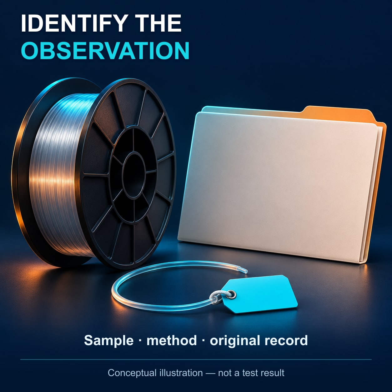
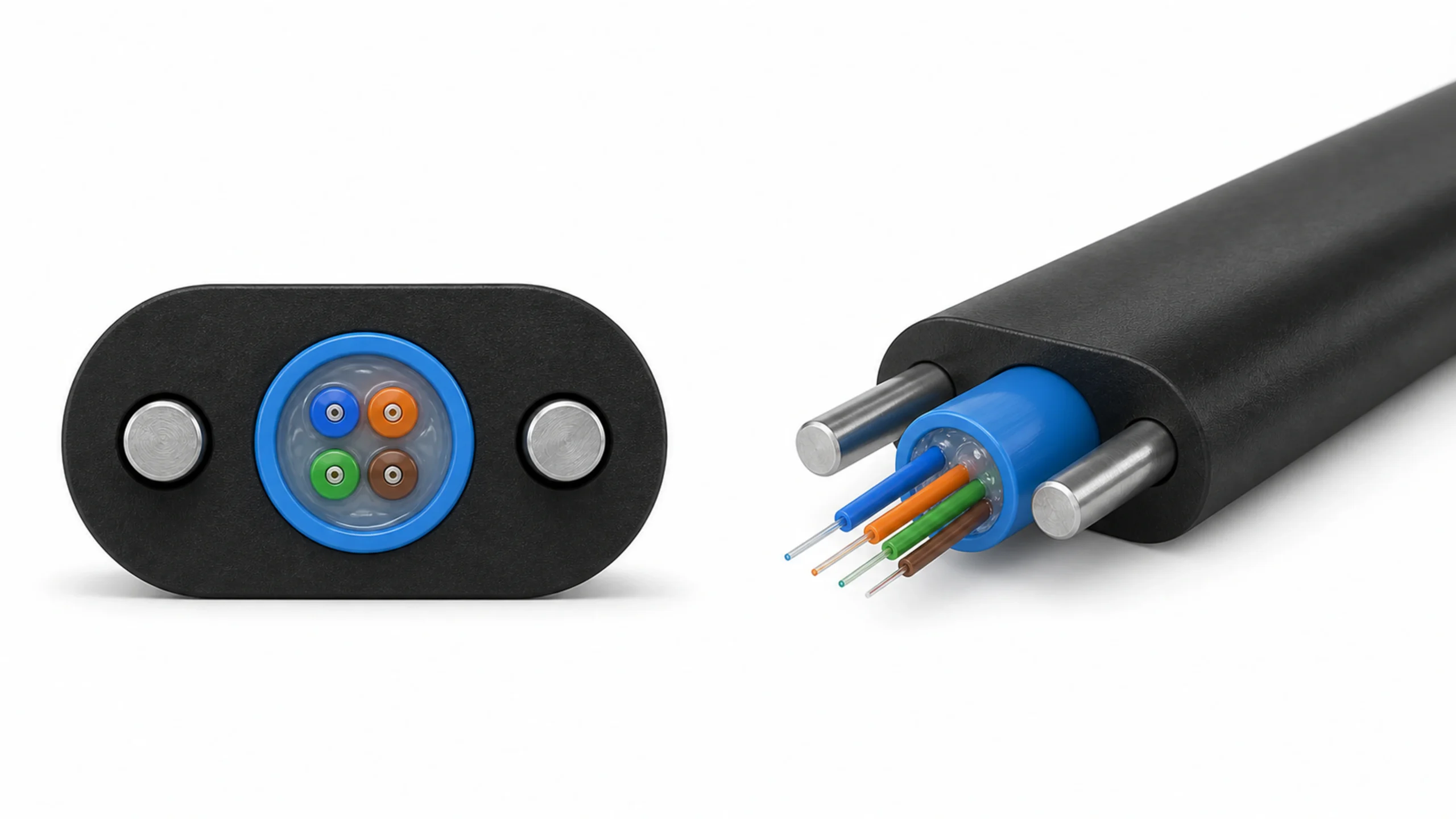
Conceptual 3D evidence-linkage illustration, not a project photograph or completed test. The reel, specimen and blank folder explain traceability; no measured result, identified lot or release is represented.
Separate the manufacturing observation from the commercial conclusion. A defect detected after sheathing is an observation about the tested cable at that point. It is not yet proof of a sheathing-machine defect, unsuitable incoming fiber or an inadequate factory layout. Those are different explanations that require different evidence.
| Observation record | Information to retain | What it prevents |
|---|---|---|
| Optical result | Identified fiber, original file or report, method, units, test settings and governing limit | Comparing unlike measurements as if they described one change |
| Physical fiber break | Identified fiber or position, observed location, time and relevant production event | Treating every break as the same failure mechanism |
| Tube or jacket defect | Sample identity, actual measured dimension or visible condition, drawing requirement and inspection method | Using a general photograph instead of a measurable nonconformity |
| Production event | Affected material range, operating state, alarm or operator observation and preserved setup record | Losing the connection between the symptom and the run |
Follow the factory’s approved hold and segregation procedure for the affected material. The investigation record should say what is on hold, who controls its disposition and which result is needed next. An unresolved sample must not become acceptable merely because another drum appears normal.
Compare the Material at Named Process Boundaries
Use the actual cable route to identify the last comparable acceptable result and the first changed result. Include transfers, storage and test preparation between those observations; the boundary is wider than the nameplate of one production machine.
A tight-buffered indoor product and a stranded loose-tube outdoor cable do not pass through an identical set of stages. Mark only the stages present in the approved route. A proposed checkpoint is not a claim that every factory already performs that test online or that every intermediate can be assessed by the same method.
For a loose-tube product, the লুজ-টিউব উৎপাদন পর্যালোচনা helps define the input-to-finished-tube boundary. That operation is not the whole outdoor-cable route, and its presence does not establish where the defect began.
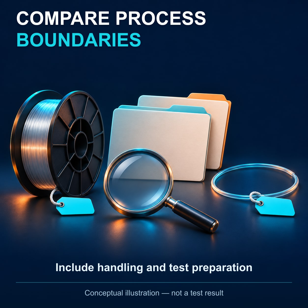
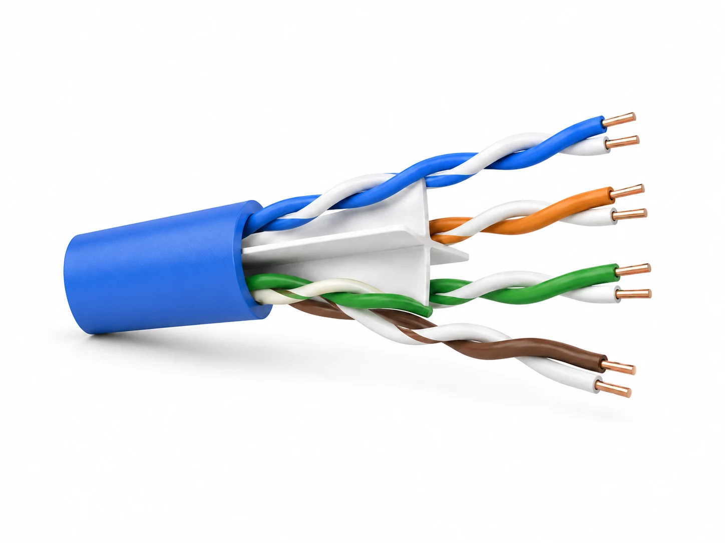
Conceptual 3D stage-comparison illustration, not a fixed cable route or actual before-and-after result. Choose only stages present in the product; associated handling and test preparation remain inside the investigation boundary.
The following matrix is an investigation-planning example, not a mandatory test schedule. Quality and engineering personnel should choose feasible sample points and methods for the identified product.
| Boundary, where present in the route | Earlier evidence to identify | Later evidence to identify | Investigation question |
|---|---|---|---|
| Incoming fiber to a prepared input reel | Supplier lot and incoming inspection record | Identified output reel and preparation record | Is there a comparable baseline before cable processing begins? |
| Fiber input to loose tube or tight-buffer output | Actual input fiber identities and baseline | Identified tube or buffered-fiber package, relevant optical and dimensional observations | What changed across this operation and its associated handling? |
| Tube packages to assembled cable core | Tube and fiber map with retained earlier results | Core identification, element map and appropriate later observations | Does the changed observation follow one element, a location or a shared operation? |
| Prepared core to sheathed cable | Core identity and last available comparable record | Finished-cable sample, sheath measurements and optical result | Is the evidence sufficient to separate a sheath defect from an optical change? |
| Cable drum to rewound or tested package | Drum identity and pre-transfer record | New package identity, handling history and repeated observation | Could the changed observation belong to the transfer or measurement boundary? |
Do not fill a missing upstream result with an assumed pass. If the earlier material was not sampled, state that the first detection point is known but the first occurrence is not. A retained input sample, an appropriate repeat trial or additional examination may help, but none should be represented as evidence that already exists.
Keep fiber identity through tube colors, core assembly and drum transfers. If the finished report names a fiber differently from the production record, reconcile the identification before assigning a process location. A measurement distance, a printed cable mark and a production timestamp should only be connected through an agreed mapping, not assumed to be interchangeable.
Confirm That the Measurements Answer the Same Question
The IEC summary for IEC 60793-1-40:2024 distinguishes cut-back, insertion-loss, backscattering and spectral-modelling methods. It also identifies backscattering as a method used to locate and characterize point discontinuities.1 An instrument name alone is therefore not enough to describe an attenuation comparison.
Before interpreting a difference, identify the method, fiber type, wavelength, test direction, specimen or length basis, relevant instrument settings and preparation procedure. Record the actual limits selected for that product. These are comparison questions, not a substitute for the applicable method or a requirement to use every method on every sample.

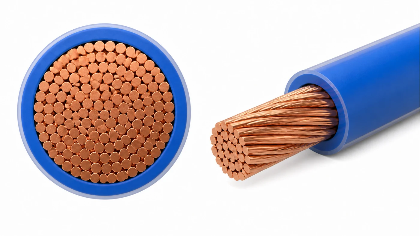
Conceptual 3D measurement-review illustration. Similar-looking specimens and blank records do not prove identical identity or test conditions. No instrument, optical trace, measured value or acceptance limit is shown.
Retain original data where the test system provides it. A screenshot can be useful evidence of what an operator saw, but it may not contain all the information needed to reproduce or review the result. Record the instrument identity and the status required by the factory’s measurement-control procedure, as well as the operator and time.
Connect the investigation to the factory optical-test evidence plan when selecting laboratory support. The required method, specimen, product limit and original record matter more than an instrument name alone.
If two results were obtained with different arrangements, mark that difference explicitly. The responsible laboratory or quality engineer should decide how to establish comparability. Do not numerically subtract unrelated results and present the difference as loss introduced by a machine.
How to verify: Select one identified fiber or sample and trace it from the production record to both measurements. Confirm that the method and conditions support the intended comparison, then retain the original records with the interpretation. If that chain cannot be completed, close the identification or measurement gap before declaring a process cause.
Keep dimensional and optical evidence separate as well. A tube or jacket can satisfy one dimensional check without that reading establishing the optical performance of every enclosed fiber. Conversely, an acceptable optical result does not resolve a separately observed sheath defect. The applicable product requirements decide which results are needed for release.
Use the Symptom to Choose an Investigation Branch
Bending-related optical loss is a reason to investigate mechanical conditions, not an automatic diagnosis. ITU-T L.100, written for duct and tunnel cable, describes microbending and macrobending as distinct loss mechanisms and discusses attenuation effects from temperature-related dimensional changes in cable elements.2 Those mechanisms do not identify the cause of a particular factory result without product-specific evidence.
For a loose-tube investigation, retain the material and cooling history rather than considering only the visible tube diameter. Maillefer’s published trial description examines excess fiber length and shrinkage alongside fiber tension, cooling-water temperature and compression conditions.3 This supports reviewing those variables together; it does not supply a universal recipe or validate a different supplier’s configuration.
If the evidence points toward a tension-controlled section, use a tension measurement and running-state review to identify the section, measurement point and observed running state. Keep a commanded setpoint separate from a measured signal; neither, on its own, proves that tension caused the defect.
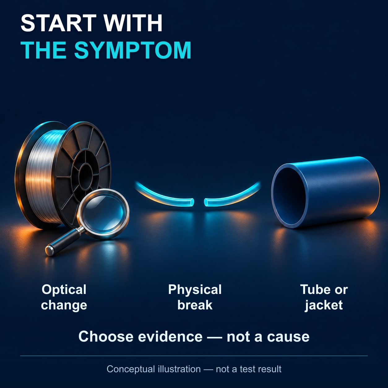
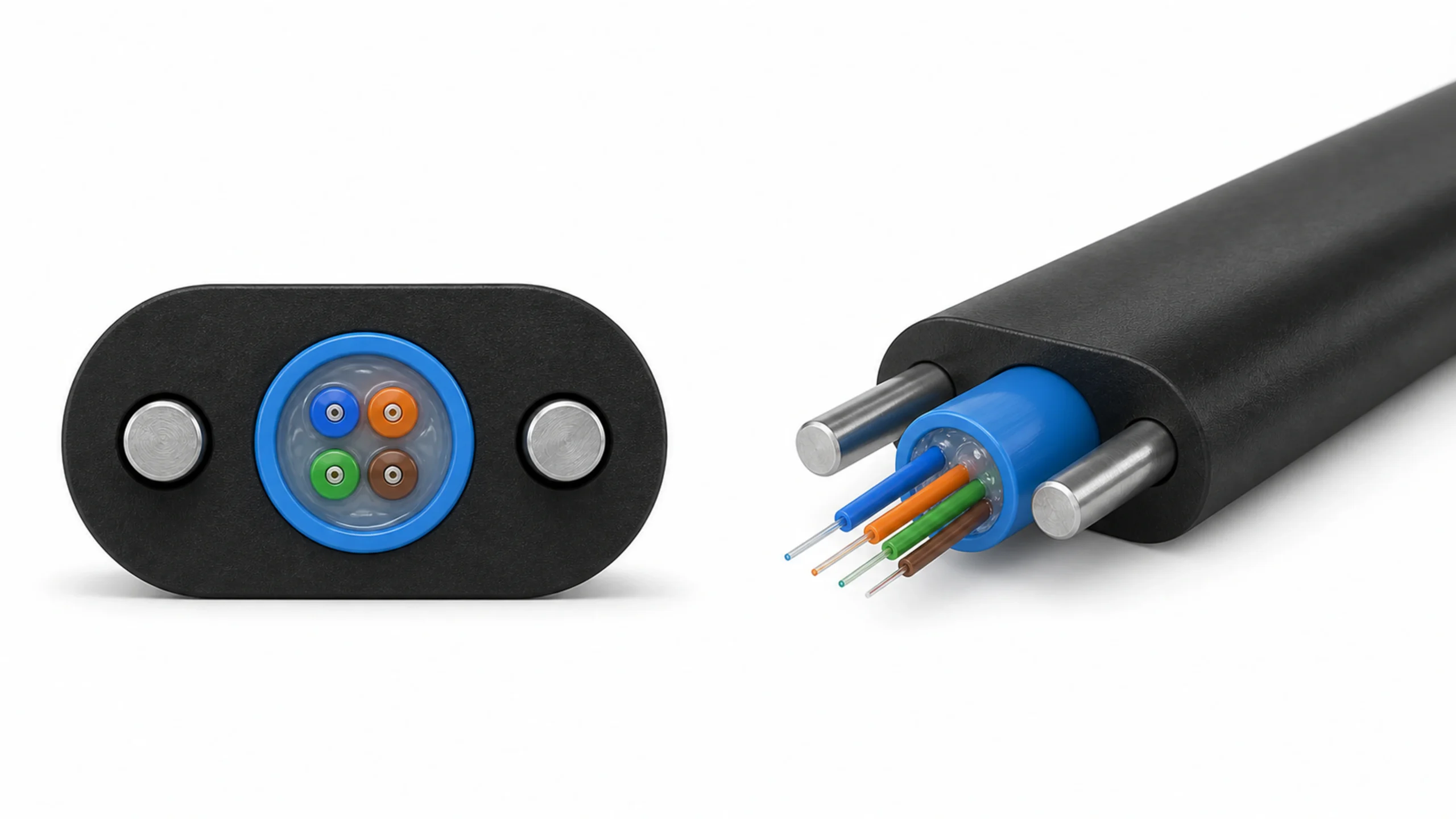
Conceptual 3D symptom symbols, not photographed defects, measured geometry or a cable construction. The separated strand and plain hollow sleeve only distinguish investigation branches; they identify no cause, setting or successful correction.
| Symptom to investigate | Evidence that helps narrow the branch | Conclusion not yet justified |
|---|---|---|
| Optical result changes without an observed break | Comparable stage results and fiber identity; compare package condition, the recorded fiber path and relevant handling or conditioning history | The extruder or one tension setting is definitely responsible |
| Fiber physically breaks during a run | Preserve the break location and affected position; compare the operating state, alarms and guide-path record with the approved setup | Lowering every tension setting is an adequate corrective action |
| Tube or jacket dimension or surface changes | Identified sample, material lot, actual measurements, approved setup and process history | The cable’s optical performance is acceptable because its surface looks better |
| A changed result appears after winding or transfer | Package identity before and after, handling record and controlled repeated measurement | The earlier production stage has been cleared without comparison |
| The observation depends on when the sample is checked | Sample condition, elapsed stage history and the agreed conditioning or test sequence | An immediate measurement proves performance after a different conditioning period |
Use the branch to define the next examination, not to issue an unsupervised adjustment instruction. Inspection of moving paths, tooling, heated areas or guarded equipment must follow the machine supplier’s instructions and the factory’s authorized safety procedures. Preserve protection functions and involve the responsible engineering personnel before a controlled trial.
Common mistakes: Several settings are changed together, the original sample is discarded, or a new material lot is introduced without recording it. A later improvement then has no clear comparison basis. Record the proposed intervention and the relevant conditions before deciding what the trial will demonstrate.
Close the Investigation with Recovery and Release Evidence
Define the recovery question before the authorized change. It may concern a repeatable optical observation, a particular fiber position, tube geometry, sheath condition or a specific operating event. The trial plan should identify the product, sample points, comparisons and acceptance criteria appropriate to that question.
Preserve the original nonconforming result. Link it to the approved intervention, the material and setup used afterward, and the repeat measurements. If more than one condition must change, document that limitation instead of claiming that a single cause has been isolated.
A useful recovery record connects:
- The suspect product, material range and original symptom.
- The earlier and later process observations, including missing evidence.
- The authorized examination or change and its responsible owner.
- The comparable repeat results and the acceptance criteria applied.
- The remaining product tests, unresolved questions and release authority.
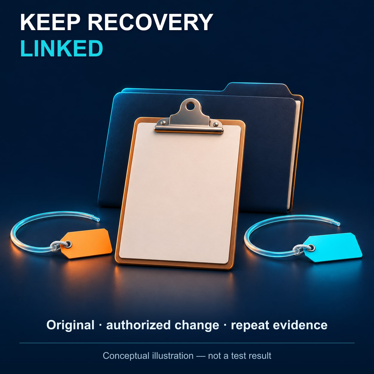
Conceptual 3D recovery-record linkage. The two specimens are separate illustrative samples, not an actual failed-and-repaired pair. The blank clipboard and folder represent records to obtain; no improvement, accepted drum or quality release is shown.
A stable machine demonstration is not the same as a finished drum’s release. Quality personnel still need the results required for the identified product and the affected material. If a laboratory or another supplier owns part of that verification, keep its responsibility and outstanding result visible.
Use the same distinction when reviewing a machinery proposal prompted by a defect. The proposal should explain which evidenced process boundary the change addresses and how its effect will be evaluated. It should not promise to cure every optical or sheath problem through a larger extruder, a new controller or a higher catalogue speed.
An investigation is useful when it leaves a defensible record: what was observed, which stage comparison narrowed the question, what was changed under authority, and what the repeat evidence actually establishes. Where the cause or a release requirement remains unresolved, preserve that open item rather than converting an improvement into an unsupported pass.
-
IEC, IEC 60793-1-40:2024 — Attenuation measurement methods. The public summary identifies different attenuation methods and the point-discontinuity scope of backscattering. The complete paid standard and its detailed procedures were not accessed for this draft; no acceptance limits are inferred from the summary. ↩
-
ITU-T, L.100 (01/2024) — Optical fibre cables for duct and tunnel application, clauses 6.1.2, 6.1.3 and 6.3.2. The cited mechanisms are contextual evidence, not a universal operating recipe or an adopted test schedule for every cable family. ↩
-
Maillefer, Superior Compression Technology. The trial description links loose-tube excess-length and shrinkage review to several process conditions. No vendor output claim, model recommendation, supplied HONGKAI system or customer result is adopted. ↩

 English
 हिन्दी
 فارسی