


Starting an optical fiber manufacturing line feels daunting, right? The investment is significant, and the technology is complex. Making the wrong equipment choices can lead to poor cable quality, production delays, and wasted capital, hurting your business before it even gets going. Understanding the essential machinery is your first critical step toward success.
Key optical fiber manufacturing equipment includes drawing towers for creating the fiber, coloring and buffering lines for protection and identification, stranding machines (like SZ stranding lines) to assemble the cable core, and jacketing lines to apply the final protective sheath. Comprehensive quality control equipment is also vital throughout.12
Getting a handle on the main stages is a good start, but the real make-or-break decisions happen when you choose the specific machines for each step. Everything from your production speed to the final cable’s performance depends on these choices. It’s easy to get lost in the technical specifications. That’s why we need to dive deeper into each critical part of the process. Let’s break down the essential equipment you’ll need, piece by piece, so you can build a reliable and efficient production line. Keep reading to understand exactly what goes into making high-quality optical fiber cables.
What Machines Are Crucial for Fiber Drawing?
Thinking about producing the actual glass fiber strand? It’s incredibly precise work. Even microscopic flaws in the fiber can cause significant signal loss later on. Using inadequate or poorly calibrated drawing equipment often results in fiber breaks during production, inconsistent diameter, and ultimately, a product that doesn’t meet performance standards.
The primary machine is the Fiber Drawing Tower1. This integrated system carefully melts the tip of a purified glass preform and pulls it into a hair-thin optical fiber, immediately applying protective coatings. Preform lathes are also needed beforehand to prepare the glass rod perfectly.
!
Let’s dive deeper into the fiber drawing process. This is arguably the most critical and technologically sensitive step in optical fiber manufacturing. The goal is to take a large, solid glass rod, called a preform, and draw it down into a continuous strand of fiber that is typically only 125 micrometers in diameter – about the thickness of a human hair – while maintaining incredibly high purity and precise geometry. Research confirms that tiny flaws introduced here can severely impact signal quality or cause breaks 2.
The Glass Preform
Everything starts with the preform. This isn’t just any glass; it’s ultra-pure fused silica. Leading manufacturers often use processes like Outside Vapor Deposition (OVD) to create preforms with exceptionally low signal loss potential. The preform itself contains the core and cladding structure needed for light transmission. Its quality directly impacts the final fiber’s characteristics. Before drawing, the preform might be inspected for flaws and mounted on a preform lathe. Here, it can be precisely shaped, cleaned, and sometimes etched to ensure a perfect starting surface. Any surface contamination or imperfection on the preform can translate into defects in the drawn fiber.
The Drawing Tower Components
The drawing tower itself is a tall, multi-story structure designed for stability and precise control. It integrates several key components working in harmony:
- Preform Feed Mechanism: This holds the preform vertically and lowers it precisely into the furnace. Controlling the feed speed is crucial for maintaining consistent fiber diameter.
- High-Temperature Furnace: This furnace operates at extremely high temperatures, typically around 2000°C (3600°F), to soften the tip of the glass preform. Graphite resistance furnaces or induction furnaces are common choices. Precise temperature control is absolutely vital; fluctuations can cause variations in fiber diameter and strength. Industry sources mention induction graphite furnaces and high-energy lasers are sometimes used.
- Diameter Measurement Gauge: Positioned just below the furnace, laser-based gauges continuously measure the fiber’s diameter as it’s drawn. This data feeds back into the control system in real-time to adjust the drawing speed (or sometimes preform feed speed) to maintain the target diameter (e.g., 125 µm) with sub-micron accuracy.
- Coating Applicators: As the bare glass fiber emerges from the furnace, it’s extremely fragile and susceptible to surface flaws from abrasion or moisture. To protect it immediately, one or two layers of UV-curable acrylate polymer coating are applied. The applicators use precise dies to ensure a concentric coating around the fiber, typically bringing the total diameter to 245-250 µm. Consistent coating thickness and concentricity are important for fiber performance and later processing.
- UV Curing Ovens: High-intensity ultraviolet lamps cure the liquid acrylate coatings rapidly, solidifying them into a protective layer before the fiber touches any mechanical components. Proper curing ensures the coating provides adequate protection and doesn’t cause signal loss (microbending).
- Capstan/Tractor Pulling System: Located near the bottom of the tower, the capstan provides the pulling force that draws the fiber from the softened preform tip. Its speed is precisely controlled, often reaching 10-20 meters per second, working in coordination with the diameter gauge feedback loop. Smooth, consistent pulling is essential.
- Tension Control System: Dancers or load cells monitor and maintain a specific, low tension on the fiber throughout the drawing process. Incorrect tension can lead to diameter variations or even breaks.
- Spooling System: Finally, the coated fiber is wound onto a large spool. Precision winding patterns are used to prevent damage and ensure the fiber can be easily unwound in subsequent processes. A single preform can yield anywhere from a few kilometers to over 25 kilometers of fiber.
I remember visiting a facility struggling with frequent fiber breaks. After checking furnace temps and alignment, we found tiny vibrations from the building’s foundation were the culprit. Installing better vibration isolation for the tower solved it. It shows how sensitive this process is. At HONGKAI, we focus on providing stable drawing tower solutions, addressing potential issues like vibration and contamination in the cleanroom environment around the furnace and coating areas 2.
How Are Fibers Colored and Buffered?
Once you have the bare, coated fiber (around 250µm), it’s still very delicate and practically invisible. Handling hundreds of these identical fibers in a cable would be impossible. Without clear identification and additional protection, field technicians face a nightmare during installation and maintenance, leading to costly errors and delays.
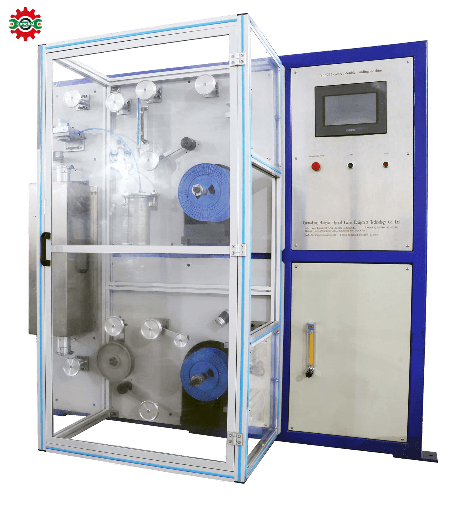
Fibers typically go through Coloring and Rewinding Lines3 first, applying UV-cured inks for identification according to standard color codes. Then, depending on the cable design, they move to Secondary Coating Lines4 to add either a tight buffer or be placed inside loose tubes for enhanced mechanical and environmental protection.
Let’s delve deeper into the coloring and buffering stages. These processes prepare the drawn fiber for assembly into a cable structure, making it easier to handle, identify, and providing the necessary level of protection for its intended application.
Fiber Coloring
The primary purpose of coloring is identification. In multi-fiber cables, each fiber needs to be uniquely identifiable. International standards (like TIA-598-C) define color codes, typically using a sequence of 12 standard colors (Blue, Orange, Green, Brown, Slate, White, Red, Black, Yellow, Violet, Rose, Aqua). For fiber counts above 12, the colors repeat, often combined with ring marks or stripes added during the coloring process, or by grouping colored fibers within different colored buffer tubes.
দ্য Coloring and Rewinding Line performs this task. Key components include:
- Pay-off Spool: Holds the spool of drawn, coated fiber (typically 250 µm diameter). Precise tension control is needed here to avoid damaging the fiber.
- Ink Applicator: This applies a thin layer of UV-curable ink onto the fiber surface. Different methods exist, including passing the fiber through an ink-filled die or using roller applicators. High-speed lines require very efficient ink application and excess removal systems (like air wipes) to ensure a smooth, uniform layer. Ring marking units might also be integrated here.
- UV Curing Oven: Similar to the drawing tower, UV lamps cure the ink rapidly. The curing energy must be sufficient to fully cure the ink without overheating the fiber or its primary coating. Advanced lines often use high-quality imported UV systems for reliability.
- Capstan and Tension Control: Pulls the fiber through the line at a controlled speed and tension. Speeds can range significantly, with modern lines reaching from hundreds up to 3000 meters per minute.
- Take-up Spooler: Winds the colored fiber onto a new spool, ready for the next stage (buffering or stranding). Precision winding is again important. Automation is key here, with systems often using PLCs (like Siemens) allowing one operator to manage multiple lines.
A challenge I often see clients face is achieving consistent color adherence and vibrancy at high speeds. Optimizing the ink formulation, UV lamp intensity, and line speed is crucial.
Secondary Coating (Buffering)
Buffering adds mechanical protection beyond the thin primary coating (250µm). There are two main types:
- Tight Buffering: In this process, one or more layers of polymer (like PVC, LSZH compounds, or sometimes nylon or Hytrel) are extruded directly over the 250 µm coated fiber, typically bringing the diameter up to 900 µm (0.9 mm). This creates a robust fiber unit that’s easier to handle and connectorize directly. It’s common in indoor cables (patch cords, distribution cables). The Tight Buffering লাইন involves:
- Fiber Pay-off(s): Handling multiple fibers simultaneously is common.
- Pre-heater: Warms the fiber slightly to promote adhesion.
- Extruder with Crosshead: Melts the buffer polymer and applies it around the fiber using a precision die. Controlling temperature and pressure is key to achieving the correct diameter and concentricity without thermally stressing the fiber. Some lines are versatile enough to handle both tight buffering and smaller "micro-sheathing" applications.
- Cooling Trough: Uses water (often warm initially, then progressively cooler) to solidify the buffer layer without introducing stress. Vacuum sections might be used for calibration.
- Diameter Gauge & Tension Control: Laser gauges monitor diameter, ensuring consistency.
- Capstan and Take-up.
- Loose Tube Buffering: Here, multiple colored fibers (typically 2 to 24, sometimes more) are laid loosely inside a polymer tube (often PBT – Polybutylene Terephthalate, known for its stability and resistance). The tube has a larger inner diameter than the bundle of fibers, allowing them freedom of movement. This isolates the fibers from external mechanical forces (like tension and bending) and allows for expansion/contraction with temperature changes, making it ideal for outdoor cables. The tubes are usually filled with water-blocking gel or contain swellable elements (yarns/tapes) to prevent water ingress. The আলগা টিউব উত্পাদন লাইন is more complex:
- Fiber Pay-offs: For multiple colored fibers (e.g., 12 or 24 pay-offs).
- Fiber Gathering/Oscillating Unit: Bundles the fibers and imparts a slight oscillation or "excess fiber length" (EFL) relative to the tube. This ensures fibers don’t take tensile load when the cable bends or contracts. Precise EFL control is critical for temperature performance.
- Extruder with Crosshead: Extrudes the PBT tube around the fiber bundle. Gel filling often happens simultaneously through the crosshead die.
- Gel Pump/Applicator: If gel-filled, precisely injects thixotropic gel using accurate metering pumps.
- Cooling Trough: Cools and solidifies the tube.
- Diameter/Wall Thickness Control: Laser gauges or ultrasonic scanners monitor dimensions.
- Capstan and Take-up (often onto large drums). Modern lines support producing tubes for 1 to 12 (or more) fibers.
Choosing between tight buffer and loose tube depends entirely on the cable application. Tight buffer offers easier handling for termination, while loose tube provides superior environmental and mechanical protection for the fibers themselves. At HONGKAI, we provide both types of secondary coating lines and help clients choose the best fit for their product mix 12. Getting the extrusion parameters right, especially for loose tubes to achieve the correct EFL, requires expertise and precise machinery control.
What Equipment Assembles Fibers into a Cable Core?
You have colored fibers, possibly protected in buffer tubes. But they’re still individual elements. How do you bring them together systematically to form the central structure of a cable? Just bundling them randomly won’t work; the cable would lack strength, organization, and consistent performance, especially under bending or tension.
Stranding Lines are used to twist the buffered fibers or loose tubes around a central strength member, forming a stable cable core. The most common type for optical cables is the SZ Stranding Line, known for its flexibility and speed. Planetary Stranding Lines are an older technology sometimes used for specific constructions.

Let’s dive deeper into the stranding process. This is where individual fibers or groups of fibers (usually within loose tubes or as tight-buffered units) are combined with other elements like strength members, fillers, and water-blocking materials to create the main structure, or "core," of the optical fiber cable. The way these elements are arranged significantly impacts the cable’s flexibility, tensile strength, size, and suitability for different installation environments.
SZ Stranding
This is the dominant method for stranding loose tubes in modern optical cable manufacturing, especially for outdoor and high-fiber-count cables. The name "SZ" comes from the fact that the tubes are stranded in a helical path, but the direction of the helix reverses periodically (e.g., several turns in the ‘S’ direction, then several turns in the ‘Z’ direction). This reversal is key.
Key features and components of an SZ Stranding Line:
- Pay-offs: These hold the spools or drums of loose tubes, tight-buffered fibers, or filler rods. They are typically stationary, meaning the spools don’t rotate around the central axis of the line. Precise tension control on each element is vital, as consistent tension ensures a uniform core structure. High-end lines focus on minimizing tension fluctuations.
- Central Member Pay-off: Feeds the central strength member (CSM), which is often a Glass Reinforced Plastic (GRP) rod or sometimes a steel wire coated in plastic. This forms the backbone of the cable core, providing tensile strength.
- Stranding Cage/Oscillator: This is the heart of the SZ strander. The tubes/fibers pass through guides on a rotating plate or cage that oscillates back and forth axially while rotating, imparting the reversing S and Z lay. This clever mechanism avoids putting a permanent twist on the tubes themselves, which is beneficial for fiber stress and allows easier mid-span access later. The oscillating mechanism also permits very high line speeds compared to planetary stranding.
- Binder Head(s): After stranding, one or two binder yarns (polyester or water-swellable yarn) are wrapped helically around the stranded core to hold the tubes together. This happens immediately after the stranding point, before the core structure can relax. Sometimes water-blocking tapes are applied here instead of, or in addition to, yarns.
- Gel Filling / Water Blocking Tape Applicator (Optional): For some designs, the interstices (gaps) between the stranded tubes might be flooded with water-blocking gel, or wrapped with water-swellable tapes, before the main binder is applied to prevent longitudinal water migration.
- Caterpillar/Capstan: Pulls the entire assembly through the line at a controlled speed. The speed, combined with the oscillation rate and rotation speed of the stranding cage, determines the "lay length" – the distance over which one complete helix (S or Z) is formed, and the reversal length. Consistent lay length is crucial for cable performance, especially flexibility and temperature stability. Advanced lines offer very stable pitch control.
- Take-up Stand: Winds the completed cable core onto a large drum, ready for the next stage (usually jacketing).
The main advantage of SZ stranding is speed and the ability to access fibers mid-span without cutting all tubes. It’s highly efficient for producing large volumes of standard loose tube cables suitable for both outdoor and indoor applications. I remember a client transitioning from older planetary equipment to a new SZ line. Their productivity increase was dramatic, but they initially struggled with getting the tube tensions exactly right during the reversals, causing slight core deformations. Fine-tuning the dancer arm controls on the pay-offs was key.
Planetary Stranding
This is an older method, though still used for certain cable types, particularly those requiring very precise geometry or involving elements that shouldn’t undergo the SZ oscillation, like metallic armored layers or some specialized hybrid cables. In a Planetary Stranding Line, the element pay-offs are mounted in a large rotating cage. As the cage rotates, the elements are laid around the central member. It’s generally slower due to the rotating masses but offers high geometric stability.
Other Core Components
Besides the fibers/tubes and the CSM, other elements are often included during stranding:
- Filler Rods: Solid plastic rods (usually PE) used to fill empty spaces in the stranding layer to maintain a round core shape, especially when the number of tubes doesn’t perfectly fill the layer.
- Water-blocking Elements: As mentioned, gels, yarns, or tapes are critical, especially for outdoor cables, to prevent water from migrating along the cable core if the jacket is breached.
Selecting the right stranding method and machinery depends heavily on the types of cables you plan to produce, the required fiber counts, and your volume expectations. At HONGKAI, we offer robust SZ stranding solutions tailored for optical cable production and guide our clients through configuring the line with the right number of pay-offs, binder types, and control systems for their needs 12.
How Is the Final Protective Layer Applied?
The stranded cable core, even with binders and water-blocking elements, is still vulnerable. It needs protection from sunlight (UV radiation), moisture, abrasion during installation, crushing forces, and potentially rodents or chemicals, depending on where it will be used. Without a tough, continuous outer layer, the cable simply wouldn’t survive the rigors of installation or its intended service life.
The final protective layer, the outer jacket or sheath, is applied using a Jacketing Line. This process involves extruding a thermoplastic material (like PE, LSZH, PVC) over the cable core. The line integrates payoffs, the extruder, cooling systems, measurement devices, printing, and take-up equipment.

Let’s explore the jacketing process in more detail. This stage gives the cable its final form, robustness, and environmental resistance. The choice of jacketing material and the quality of its application are critical for the cable’s longevity and performance in its specific environment (e.g., indoor, outdoor, aerial, direct burial, industrial).
The Jacketing Line Components
A typical Optical Cable Jacketing Line consists of several integrated sections working together smoothly:
- Core Pay-off: Holds the drum of stranded cable core coming from the stranding line. Smooth payoff with controlled tension is essential to feed the core without disturbance into the extruder.
- Strength Member / Armor Pay-offs (Optional): Some cable designs incorporate additional strength members (aramid yarns like Kevlar®, fiberglass yarns) or metallic armor (corrugated steel tape for rodent protection, steel wires for tensile strength) applied under the main jacket or integrated সঙ্গে it. Pay-offs for these elements are positioned before the extruder crosshead. Ripcords, thin but strong threads placed under the jacket, are also added here to allow technicians to easily tear open the jacket for accessing the core without damaging the fibers.
- Extruder: This is the core machine for melting thermoplastic pellets (e.g., High-Density Polyethylene – HDPE for outdoor, Low Smoke Zero Halogen – LSZH for indoor safety, Polyvinyl Chloride – PVC for general purpose) and pumping the molten polymer. It consists of a hopper for pellets, a precisely heated barrel with a rotating screw designed specifically for the type of polymer being processed, and drive motors. Precise temperature control along the barrel zones (often using advanced controllers like Omron) is critical for proper melting, consistent output viscosity, and avoiding material degradation.
- Crosshead Die: Attached to the end of the extruder, the crosshead guides the cable core through its center while molten plastic flows through internal channels around it and out through a precision die-and-tip assembly. This forms the jacket layer around the core. The design of the crosshead tooling (tip and die) is critical for achieving the correct jacket thickness, concentricity (uniform thickness all around), and surface finish. Pressure tooling or tube-on tooling (with vacuum sizing) configurations exist depending on the material and desired finish.
- Cooling Trough: Immediately after the crosshead, the cable enters a long trough filled with water. Cooling needs to be gradual and controlled (often starting with warmer water, then progressively cooler sections) to solidify the jacket without introducing internal stresses, shrinkage issues, voids, or deformation. High-speed lines require very long or efficient multi-pass cooling troughs.
- Dryer: Air wipes or high-speed blowers remove residual water from the cable surface before measurement and printing.
- ব্যাস গেজ: Laser gauges continuously measure the final outer diameter of the cable, feeding back information to potentially adjust extruder screw speed or capstan speed for control. Wall thickness might also be monitored ultrasonically or with X-ray gauges for critical applications.
- Spark Tester (Optional): For cables requiring high electrical integrity or specific quality checks, this device applies a high voltage to the cable surface to detect pinholes or breaches in the jacket.
- Inkjet Printer: Prints identification markings, manufacturer name, cable type, fiber count, batch numbers, and sequential length markings directly onto the jacket surface. Good ink adhesion and legibility under various conditions are important. Modern systems can link with factory MES/ERP systems for tracking.
- Caterpillar/Capstan: Provides the main pulling force for the entire line, carefully synchronized with the extruder output to maintain dimensional stability and prevent stretching or slack.
- Accumulator (Optional): A vertical or horizontal tower that stores a length of cable, allowing continuous line operation during the time it takes to change over the full take-up reel to an empty one.
- Take-up Stand: Winds the finished cable onto large shipping reels or drums. Precision winding patterns (level winding) and controlled tension are necessary to prevent damage to the cable during storage and transport.
Jacketing Materials and Considerations
- HDPE: Excellent moisture resistance, UV stability (when compounded with carbon black), and abrasion resistance. The standard for most outdoor cables.
- LSZH: Low smoke emission, zero halogen content, flame retardant properties. Required by regulations for safety in many indoor and confined spaces (buildings, tunnels, ships). Can be more challenging to process than PE or PVC, requiring specific screw designs and temperature profiles.
- PVC: General purpose, flexible, relatively low cost, but produces heavy smoke and toxic, corrosive hydrogen chloride gas when burned. Its use is declining in many regions and applications due to safety and environmental concerns.
- TPU (Thermoplastic Polyurethane): Offers high flexibility, excellent abrasion resistance, and good oil/chemical resistance, often used for specialty, industrial, or tactical cables.
I recall working with a customer setting up an LSZH jacketing line 5. They faced issues with surface roughness and inconsistent diameter. We traced it back to their screw design not being optimal for the LSZH compound, combined with suboptimal temperature settings. By recommending adjustments and minor tooling modifications, we helped them achieve a smooth, consistent jacket meeting all specs. Choosing the right extruder screw, crosshead design, and having precise temperature and speed control are paramount. HONGKAI supplies complete jacketing lines, including high-speed options suitable for various optical cable designs, and provides the process expertise needed to handle different materials effectively 2.
What Testing Equipment Guarantees Cable Quality?
You’ve manufactured the cable, passing it through drawing, buffering, stranding, and jacketing. But how do you know it meets the required optical performance and mechanical durability standards? Shipping faulty cable leads to failed installations, network downtime, huge remedial costs, and severe damage to your reputation. Simply hoping for the best isn’t an option.
Comprehensive testing using specialized equipment is essential. Key instruments include Optical Time Domain Reflectometers (OTDR) for checking fiber integrity and loss, Light Source/Power Meters for insertion loss/return loss, environmental chambers for temperature/humidity cycling, and mechanical testers for tensile strength, crush, and bend performance.6

Let’s dive deeper into the critical role of testing and quality control (QC) in optical fiber cable manufacturing. It’s not just a final check; QC should be integrated throughout the entire production process, from incoming raw materials (like glass preforms, buffering compounds, jacketing pellets) 3 to the final finished product ready for shipment. This ensures that any deviations are caught early, minimizing waste and guaranteeing that the cable delivered to the customer meets or exceeds specifications. Rigorous testing is non-negotiable.
In-Process Testing
Many quality checks happen continuously or semi-continuously during manufacturing:
- Fiber Drawing: Continuous diameter monitoring, coating concentricity checks, online tensile strength proof testing (briefly stressing the fiber to weed out weak points).
- Coloring/Buffering: Color verification against standards, diameter checks (e.g., 900µm for tight buffer), coating adhesion tests.
- Loose Tube: Excess Fiber Length (EFL) measurement verification (critical for temperature performance), tube geometry (diameter, wall thickness) checks.
- Stranding: Lay length verification, core diameter checks, binder tension control monitoring.
- Jacketing: Continuous outer diameter and wall thickness monitoring, spark testing (if specified), print quality checks (legibility, durability).
Final Cable Testing (Optical Performance)
Once the cable is manufactured, comprehensive optical tests are performed on sampled or all fibers, usually from end-to-end on the final reel. Key tests include:
- Attenuation Measurement (Insertion Loss): This measures the signal loss per unit length (dB/km) at specific transmission wavelengths (e.g., 850nm, 1300nm for multimode fibers; 1310nm, 1550nm, sometimes 1625nm for single-mode fibers). The standard method uses a stabilized Light Source and Optical Power Meter (LSPM). For full reel measurements, an OTDR is often used. Low attenuation is fundamental for transmitting signals over distance.
- Optical Time Domain Reflectometer (OTDR) Testing: An OTDR acts like radar for light. It sends short, high-power light pulses down the fiber and measures the timing and intensity of light scattered back (Rayleigh scattering) or reflected back from points along the fiber. This allows detection and precise localization of events like breaks, splices, connectors, sharp bends (macrobends), and the end of the fiber. It provides a visual trace (graph) of loss versus distance, confirming fiber continuity and uniformity across the entire cable length. It’s invaluable for verifying the integrity of every fiber path within the reel before shipping.
- Return Loss (RL): Measures the amount of light reflected back towards the source, particularly important at connection points (though measured end-to-end on the reel too). High reflectance can destabilize laser sources and impair network performance. Specialized RL meters or capable OTDRs measure this.
- Chromatic Dispersion (CD): Measures the spreading of light pulses caused by different wavelengths (colors) of light traveling at slightly different speeds within the fiber core. This becomes a limiting factor for high-speed (e.g., 10 Gbps and above) long-distance single-mode systems. Requires specialized test equipment.
- Polarization Mode Dispersion (PMD): Measures pulse spreading caused by different polarization states of light traveling at slightly different speeds, usually due to slight imperfections or stresses causing birefringence in the fiber. Also critical for very high bit-rate systems (40 Gbps, 100 Gbps and above). Requires specialized equipment.
- Cutoff Wavelength (for single-mode fiber): Determines the shortest wavelength above which the fiber reliably guides only a single light path (mode). This needs to be lower than the intended operating wavelengths (like 1310nm) to ensure true single-mode operation.
Final Cable Testing (Mechanical and Environmental)
| These tests ensure the cable structure can withstand the physical stresses of installation and operate reliably in its intended environment. They are typically performed on representative samples according to international standards (like IEC 60794 series or Telcordia GR-20). | Test Type | Purpose | Typical Monitoring |
|---|---|---|---|
| প্রসার্য শক্তি | Simulates pulling forces during installation (in ducts, aerial). Checks for fiber strain and attenuation increase. | Load applied, Attenuation | |
| Crush Resistance | Simulates being squeezed or run over. Checks for fiber breaks or attenuation increase. | Force applied, Attenuation | |
| Impact Resistance | Simulates sharp blows (e.g., dropped tool). Checks for physical damage and fiber integrity. | Impact energy, Attenuation | |
| Bend Performance | Tests performance under repeated bending or sustained bending at minimum radius. Checks for attenuation increase. | Bend radius/cycles, Attenuation | |
| Torsion/Twist | Simulates twisting forces during installation. Checks for damage. | Twist cycles, Attenuation | |
| Temperature Cycling | Simulates operation in changing outdoor/indoor temperatures (e.g., -40°C to +70°C). Crucial test. | Temp range/cycles, Attenuation | |
| Water Penetration | Verifies effectiveness of water-blocking elements (gel, tapes, yarns). Checks for water migration distance. | Water head/time, Distance | |
| Dimensional Checks | Verifies final cable diameter, jacket thickness, concentricity using calipers, micrometers, profile projectors. | Measurements vs Spec |
Industry standards often specify demanding requirements, for example, certain cables must withstand significant tensile forces (sometimes specified in Newtons or kg-force, where values equivalent to several hundred kilograms are common for robust designs) without significant increases in fiber attenuation.
Having the right testing equipment and, more importantly, implementing a rigorous QC plan 4, is non-negotiable. It builds confidence in your product and prevents costly failures. While HONGKAI focuses on providing the manufacturing machinery 2, we always emphasize the importance of integrating robust testing protocols and can advise on the necessary equipment based on the cable types being produced and the standards they need to meet. We ensure the equipment we deliver produces cable that can pass these rigorous tests 6.
উপসংহার
Choosing the right optical fiber manufacturing equipment is vital for success. From precise fiber drawing towers and protective coloring/buffering lines, through structured SZ stranding and robust jacketing extruders, to rigorous quality testing stations, each stage requires reliable, high-performance machinery 1. Investing wisely in an integrated production line ensures quality, efficiency, and the ability to meet demanding market needs. HONGKAI offers comprehensive solutions and expertise to help you build your complete optical cable manufacturing capability, from start to finish 42.
-
HONGKAI offers solutions for optical cable production lines and cable making machines. Source: https://hkcablemachine.com/ ↩ ↩ ↩ ↩ ↩
-
HONGKAI is a leader in fiber optic, electric & lan cable production technologies, offering top-notch solutions and equipment for fiber optic cables. Source: https://hkcablemachine.com/ ↩ ↩ ↩ ↩ ↩ ↩ ↩ ↩
-
HONGKAI provides raw materials for cables. Source: https://hkcablemachine.com/ ↩ ↩
-
HONGKAI works with clients through discussing solutions, producing equipment, checking/testing products, and installation/training. Source: https://hkcablemachine.com/ ↩ ↩ ↩
-
HONGKAI provides electric cable production lines (which share jacketing technology with fiber optic lines). Source: https://hkcablemachine.com/ ↩
-
HONGKAI performs industry standard tests on products made by their equipment using customer-provided data/materials before shipment and offers installation/commissioning/training support. Source: https://hkcablemachine.com/ ↩ ↩


